4 Operating elements and
displays
BA.GB.12-27409-05-07-FTA-jr
4.2 Operating elements and displays of the chassis
Operation of the chassis can be gathered from the operating instructions of
the chassis-manufacturer.
4.3 Operating elements and displays of the Ruthmann-
Steiger
4.3.1 Operating elements and indications on the instrument panel in
the driver’s cab
On the switch board of the instrument installation, the switch „Power take-
off“ (main switch) is situated on the left near the steering wheel. By means
of this switch the hydraulic pump drive operation as well as the Steiger are
switched on and/or off at the same time. Please also see Operating Manual
of chassis manufacturer.
There are two additional pilot lamps at the switch board. The pilot lamps
signals that the Steiger is not in its transport position. They extinguish,
when operation of the Steiger is switched off and the subsequent signals of
the sensory mechanism contact.
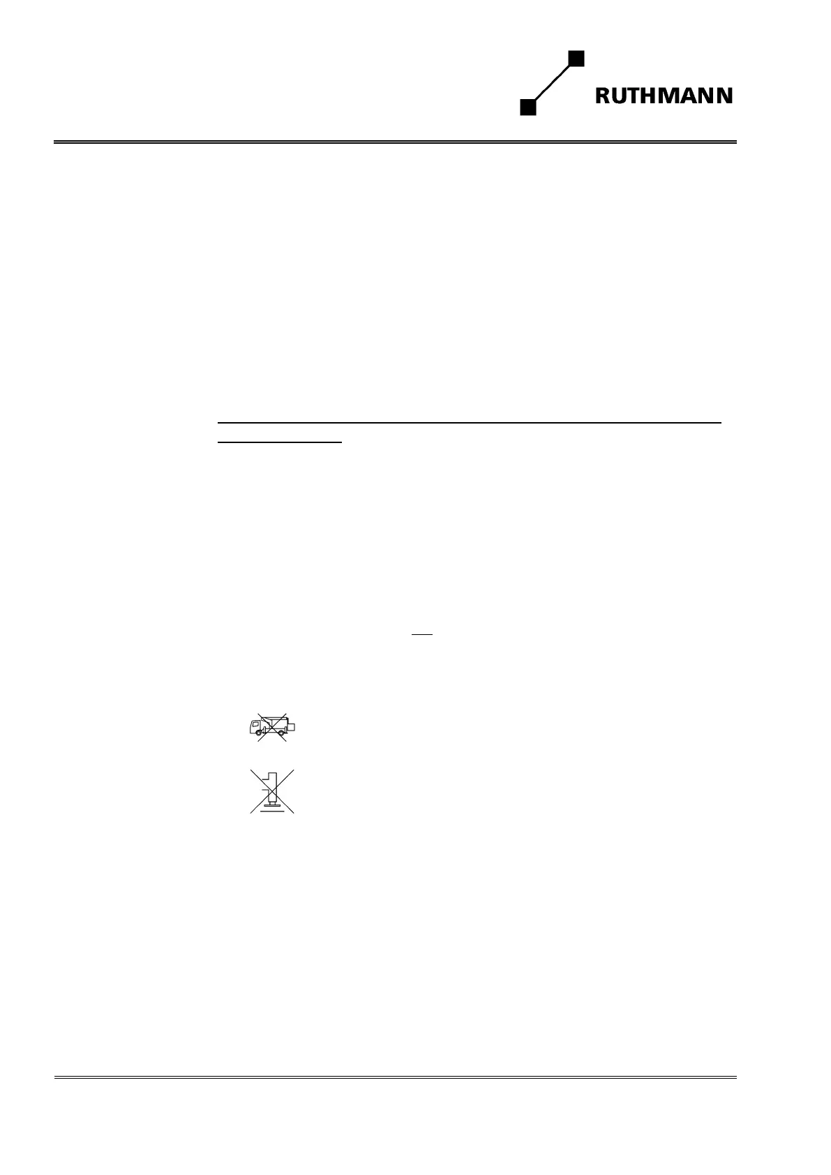
Pilot lamp
„Steiger not in
transport position“
extinguishes if:
Boom system in its boom rest.
Pilot lamp
„Stabilizing jacks not
in basic position“
extinguishes if:
Stabilising jacks retracted.
The form and position of the switch and/or the pilot lamps can slightly
change depending on the outfit of the carrier chassis (please also see Op-
erating Manual of chassis manufacturer).
 Loading...