■
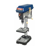
TABLE ADJUSTMENT
•
Height Adjustment (Fig 1)
To adjust up or down, loosen
the clamping lever, them adjust
the table to the desired position
and re-tighten clamping lever
securley.
•
Tilting Adjustment
(Fig 2 & 3)
Loosen pivot bolt. Tilt table to
desired angle up to 45° and
re-tighten bolt.
•
Swing 360°:
Loosen clamping lever then
swing table to appropraite
position and retighten.
•
Rotate 360°:
Loosen clamping lever, rotate
table to desired position and
retighten.
■
DEPTH ADJUSTMENT
•
Feed Depth Adjustment
(Fig 4)
Lower spindle assembly to
desired depth and spin down
nut. If nut moves due to vibra-
tion, spin down second nut and
lock in position by holding the
lower nut and tightening upper
nut.
•
Speed Adjustment (Fig 5)
Open pulley cover. Loosen
shifter bar. Choose speed for
drilling operation and move belt
to correct position for desired
speed. Push motor backward
until moderate belt tension is
acquired. Tighten shifter bar.
•
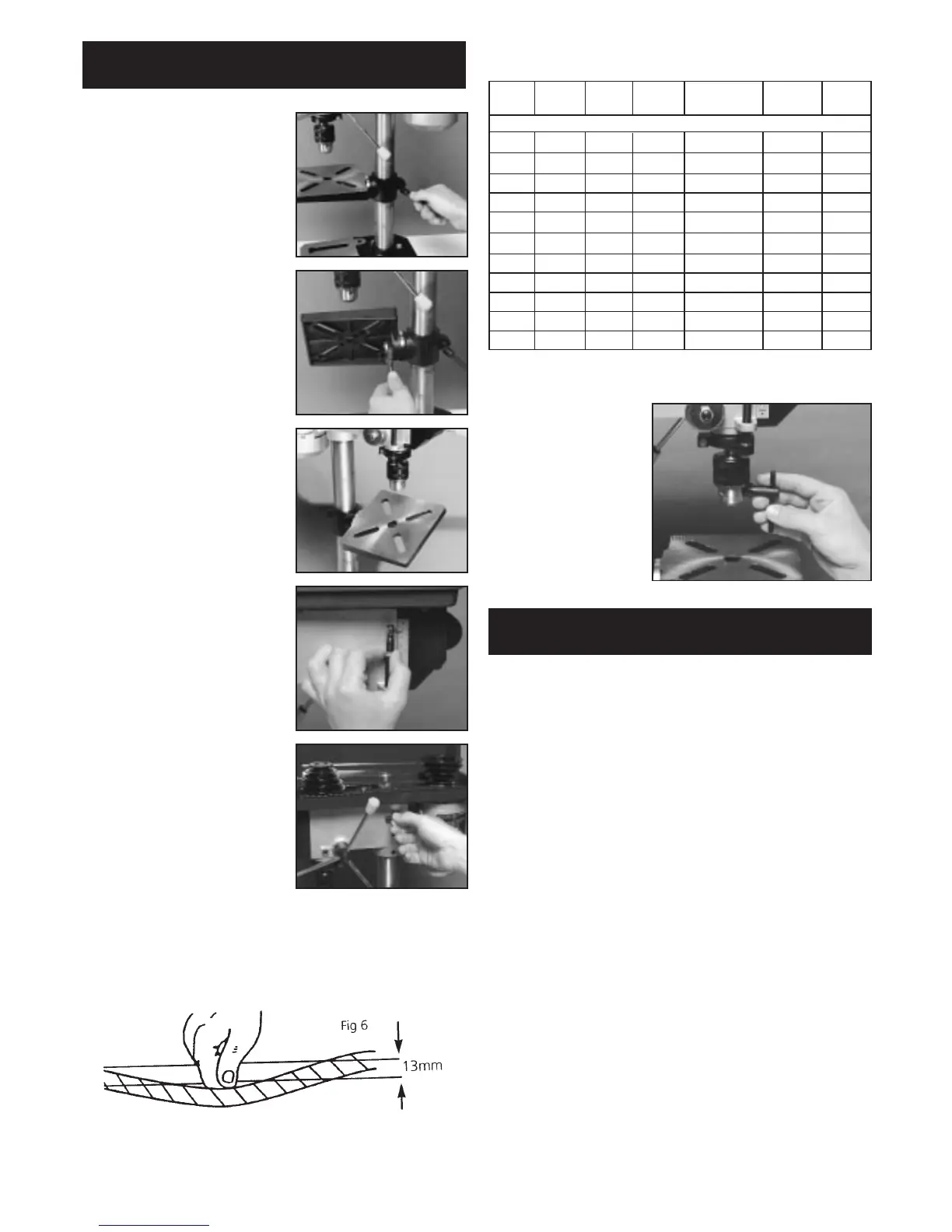
Belt Tension Adjustment
(Fig 6)
To guage proper belt tension,
use pressure to push down
with the thumb thumb on the belt at midway point
between the two pulleys. The belt should push down no
more than 13mm.
■
INSTALLING DRILL BITS
Open chuck jaws with chuck key (Fig.7).
Insert drill bit into chuck
jaws approx. 25mm.
When using a small drill
bit, do not insert it so
far that the jaws touch
the arbor of the drill.
Make sure that the drill
bit is centred in the
chuck before tightening
the chuck with the key.
Tighten all 3 holes.
■
DRILLING
Use clamps to hold the workpiece when drilling. The
workpiece should never be held by hand as the lips of the
drill may seize the workpiece at any time, especially
when breaking through the stock.
If the workpiece is whirled outof the operators hand,
injury may occur.
For flat work, lay the workpiece on a wooden base and
clamp it firmly down against the table to prevent it from
turning.
•
Using Vice
For small workpieces that cannot be clamped to the
table, use a drill press vice (not included). The vice must
be clamped or bolted to the table.
•
Positioning Workpiece
Always place a piece of wood on the table. This will pre-
vent splintering or making heavy burs on the underside
of the workpiece as the drill breaks through. The wood
must contact the left side of the column.
•
Round-Out Tolerance
For drilling operations requiring close tolerances, place
drill blank into chuck and check run out with a dial indica-
tor. If the run out is not within desired tolerance, tap the
chuck bottom with a rubber mallet until you get the
desired tolerance.
ADJUSTMENT
The proper drill speed for a given drill bit size
is as follows:
DRILL STEEL CAST METAL ALUMINIUM PLASTIC WOOD
DIA IRON
(mm)
ROTATIVE SPEED R.P.M.
3 2500 2500 2500 2500 2500 2500
4 2500 2500 2500 2500 2500 2500
5 1750 2500 2500 2500 2500 2500
6 1750 2500 2500 2500 2500 2500
7 1250 1750 2500 2500 2500 2500
8 1250 1750 2500 2500 2500 2500
9 900 1250 1750 2500 2500 2500
10 900 1250 1750 1650 2500 2500
11 625 900 1250 1250 1750 1750
12 625 900 1250 1250 1750 1750
13 625 625 900 1250 1250 1750
OPERATION
Fig 1.
Fig 2.
Fig 3.
Fig 4.
Fig 5.
 Loading...