11 — English
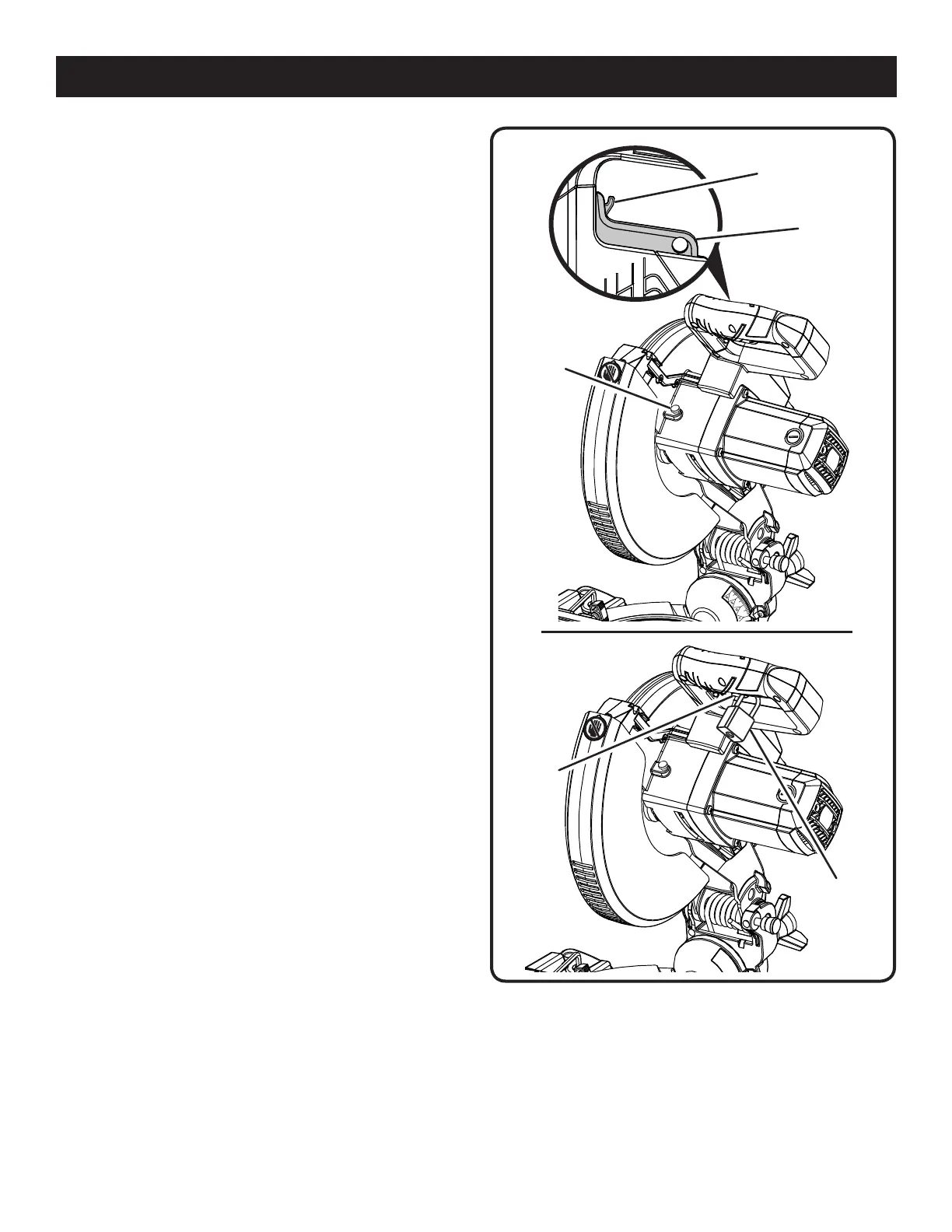
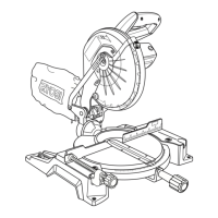
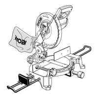
SPINDLE
LOCK
BUTTON
PADLOCK
SWITCH
TRIGGER
Fig. 4
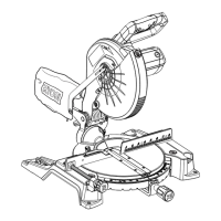
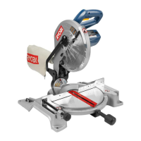
FEATURES
PARTIAL SLIDING FENCE
The partial sliding fence on your compound miter saw has
been provided to help secure the workpiece when making
straight cuts.
The sliding feature makes it easy to adjust the position of the
partial fence. Loosen the fence screw before attempting to
slide the partial fence. Once the desired position is determined,
tighten the fence screw to secure.
POSITIVE STOPS ON MITER TABLE
Positive stops have been provided at 0°, 15°, 22-1/2°, 31.6°,
and 45° on both the left and right side of the miter table.
SELF-RETRACTING LOWER BLADE GUARD
The lower blade guard is made of shock-resistant, see-
through plastic that provides protection from each side of
the blade. It retracts over the upper blade guard as the saw
is lowered into the workpiece.
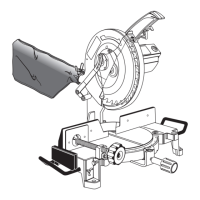
SPINDLE LOCK BUTTON
See Figure 4.
The spindle lock button locks the spindle stopping the
blade from rotating. Depress and hold the lock button while
installing, changing, or removing blade.
SWITCH TRIGGER
See Figure 4.
The saw will not start until you depress the trigger lockout lever
and squeeze the switch trigger. To prevent unauthorized use
of the compound miter saw, disconnect it from the power
supply and lock the switch in the OFF position. To lock the
switch, install a padlock (not included) through the hole in
the switch trigger and make certain the switch is inoperable.
If the switch is still operable with the padlock installed, a
padlock with a larger shackle diameter must be used. Store
the padlock key in another location.
SWITCH
TRIGGER
TRIGGER
LOCKOUT LEVER