17 − English
45
30
15
0
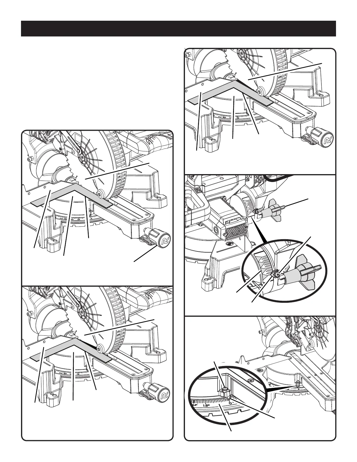
ASSEMBLY
Release the detent release lever, and ensure the control
arm is seated in the positive notch.
Tighten the miter lock knob to secure the miter table.
Loosen bevel lock knob and set saw arm at 0° bevel (blade
set 90° to miter table). Tighten bevel lock knob.
Lay a square flat on the miter table. Place one leg of the
square against the fence. Slide the other leg of the square
against the flat part of saw blade.
NOTE: Make sure that the square contacts the flat part of
the saw blade, not the blade teeth.
MITER
LOCK HANDLE
Fig. 16
MITER
TABLE
VIEW OF BLADE SQUARE WITH FENCE
SQUARE
VIEW OF BLADE NOT SQUARE WITH
FENCE, ADJUSTMENTS ARE REQUIRED
Fig. 17
MITER
FENCE
MITER
TABLE
BLADE
BLADE
SQUARE
MITER
FENCE
Fig. 18
Fig. 19
Fig. 20
VIEW OF BLADE NOT SQUARE WITH
FENCE, ADJUSTMENTS ARE REQUIRED
MITER
TABLE
SQUARE
MITER
FENCE
INDICATOR
SCREW
BEVEL
SCALE
BLADE
SCALE
INDICATOR
INDICATOR
SCREW
MITER SCALE
BEVEL
LOCK KNOB
45
30
15
0
SCALE
INDICATOR
 Loading...