USER MANUAL - SIP POWER ION PUMP CONTROLLER
M.HIST.0109.23 Rev.1 Page 27 of 62
8. THE OUTPUT CONNECTOR FUNCTION
The output connectors can be used for a possible connection of a device designed for monitoring
or controlling the supply activity.
The IN/OUT INTERFACE is intended for connection to protective hardware systems;
the LAN connector can be utilized for communication purposes via ETHERNET interface
the USB connector can be utilized to record the device parameters on a USB flash memory
the RS485 connector (in the version without display) can be utilized for communication purposes
via RS485 interface in MODBUS protocol.
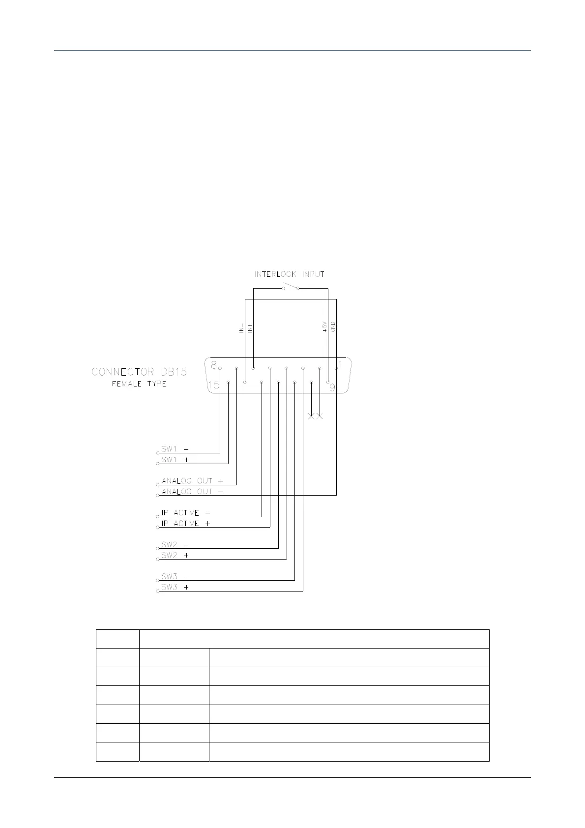
8.1. Pin layout of IN/OUT Interface connector
Pin Meaning
1 GND output of negative feeding voltage
2 not used
3 SW3+ positive terminal of comparator switch 3
4 SW2+ positive terminal of comparator switch 2
5 IP active + positive terminal of switch Operation IP on
6 IN + positive terminal of control input INTERLOCK