Do you have a question about the SAES SIP POWER and is the answer not in the manual?
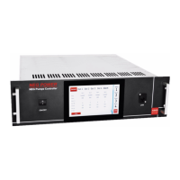
Provides a detailed overview of the SIP POWER controller's features and capabilities.
Explains the software for remote control via Ethernet and RS485 for multiple units.
Illustrates the internal functional blocks and connections of the SIP POWER unit.
Depicts the overall system connection diagram, including peripherals and pumps.
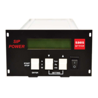
Details the components and controls located on the front of the SIP POWER unit.
Identifies and describes the connectors and ports on the rear of the SIP POWER unit.
Highlights the LEDs and RS485 interface on the front panel of the SIP POWER.
Lists the standard accessories included with the SIP POWER controller.
Specifies the physical dimensions and weight of the SIP POWER instrument.
Describes how to mount the SIP POWER unit as a stand-alone or in a rack.
Details the power supply and electrical connection requirements for the SIP POWER.
Explains the procedure for powering on and initializing the SIP POWER unit.
Guides on how to switch on and operate the Ion Pump (IP) supply.
Details the function and operation of the comparator switches (SW1, SW2, SW3).
Describes the behavior of the SIP POWER during power line interruptions.
Explains the layout and information shown on the SIP POWER's alphanumeric display.
Details the functions of the keys on the front panel and their use in different modes.
Provides the pinout diagram and meaning for the IN/OUT interface connector.
Describes the analog output signal for current/pressure and its scaling.
Details the RS485 interface standard, pinout, and communication parameters.
Outlines the Modbus Application Protocol version and implemented functions.
Lists the Modbus registers with their addresses, names, and descriptions.
Provides a detailed explanation of each Modbus register's bits and purpose.
Describes the payload structure for setting working parameters via UDP.
Explains the payload format for setting IP address and network mask via UDP.
Details the payload structure returned by the device for the "Read All" command.
Provides guidance on troubleshooting common messages and issues during IP operation.
Lists contact information and locations for SAES sales and service centers globally.
| Brand | SAES |
|---|---|
| Model | SIP POWER |
| Category | Controller |
| Language | English |