USER MANUAL - SIP POWER ION PUMP CONTROLLER
M.HIST.0109.23 Rev.1 Page 3 of 62
INDEX
1. APPLICATION ......................................................................................................................... 5
2. INTRODUCTION ..................................................................................................................... 5
2.1. General description ......................................................................................................... 5
2.2. Remote and multi Control ............................................................................................... 5
2.3. Simplified block scheme ................................................................................................. 7
2.4. Scheme of the instrument connection ............................................................................. 7
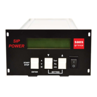
2.5. The front panel of the unit ............................................................................................... 8
2.6. The rear panel of the unit ................................................................................................ 8
2.7. The front panel of the unit with LEDs and RS485 interface .......................................... 10
2.8. Supplied accessories .................................................................................................... 10
2.9. Instrument Dimensions and Weight .............................................................................. 11
3. INSTALLATION ..................................................................................................................... 12
3.1. Mounting operation ....................................................................................................... 12
3.2. Electrical connections ................................................................................................... 14
4. OPERATIONS ....................................................................................................................... 15
4.1. Start operations ............................................................................................................. 15
4.2. Operating IP supply ...................................................................................................... 15
4.3. Comparators with simple threshold or hysteresis ......................................................... 16
4.4. Operating IP in case of main line interruption ............................................................... 17
5. DISPLAY AND MULTIPLE FUNCTIONS OF KEYS .............................................................. 18
5.1. Display information ....................................................................................................... 18
5.2. Multifunctional keys ....................................................................................................... 20
6. SETTINGS and SERVICE MODE MENU .............................................................................. 22
Vout Set Point ............................................................................................................................ 22
Vout Ramp Intv ................................................................................................................
........... 22
Conversion Rate ......................................................................................................................... 22
SW1 Mode and SW1 Thr. ........................................................................................................ 22
SW2 Mode and SW2 Min Thr. and SW2 Max Thr. ................................................................. 22
SW3 Mode and SW3 Min Thr. and SW3 Max Thr. ................................................................. 23
IP Address, IP Netmask and MAC Address ............................................................................. 23
Keepalive .................................................................................................................................... 23
Backlight Sleep ........................................................................................................................... 23
Active Time ................................................................................................................................. 23
Int. Temperature ......................................................................................................................... 23
Card Type ................................................................................................................................... 23
Hw. Rev. and Sw. Ver. ............................................................................................................... 24
Serial Number ............................................................................................................................ 24
7. ABNORMAL SITUATION AND ALARM NOTIFICATION ...................................................... 25
Interlock ...................................................................................................................................... 25
Safe ............................................................................................................................................ 25
Arcing ......................................................................................................................................... 25
Over current ............................................................................................................................... 25
Over temperature ....................................................................................................................... 25
Input voltage ............................................................................................................................... 26
Output over-voltage .................................................................................................................... 26
Communication .......................................................................................................................... 26
8. THE OUTPUT CONNECTOR FUNCTION ............................................................................ 27
8.1. Pin layout of IN/OUT Interface connector ..................................................................... 27
8.2. Analog Output ............................................................................................................... 28
8.3. RS485 Interface ............................................................................................................ 29