VG5 Installation & Quick-Start Manual 35
Control Circuit Wiring
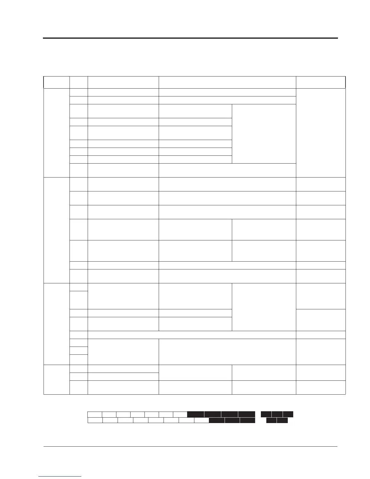
The table below outlines the functions of the control circuit terminals.
Control Circuit Terminals
Classification
Termi-
nal
Signal Function Description Signal Level
Sequence
Input Signal
1 Forward run/stop Forward run when closed, stop when open (2-wire configuration)
Photo-coupler insulated
Input: +24VDC, 8mA
2 Reverse run/stop Reverse run when closed, stop when open (2-wire configuration)
3 External fault input
Fault when closed, normal state
when open
Multi-function contact inputs
(H1-01 to H1-06)
4 Fault reset input Reset when closed
5
Master/Aux. change
Multi-step speed ref.1)
Aux. freq. ref. when closed
6 Multi-step speed ref.2 Effective when closed
7 Jog reference Jog run when closed
8 External baseblock Inv. output baseblocked when closed
11
Sequence control input common
terminal
—
Analog
Input Signal
15
+15V
Power supply output
For analog command +15V power supply
+15V (Allowable current
20mA max.)
33
-15V
Power supply output
For analog command -15V power supply
-15V (Allowable current
20mA max.)
13 Master frequency ref. (voltage)
-10 to +10V/-100% to +100%
0 to +10V/100%
-10 to +10V (20k),
0 to +10V/(20k)
14 Master frequency ref. (current) 4 to 20mA/100%.
Multi-function analog input (H3-
08, H3-09,
H3-10, H3-11)
4 to 20mA (250)
16 Multi-function analog input
-10 to +10V/-100% to +100%
0 to +10 V/100%
Multi-function analog input (H3-
04, H3-05,
H3-06, H3-07)
-10 to +10V (20k),
0 to +10V/(20k)
17 Common terminal for control circuit 0V —
12
Connection to shield sheath of
signal lead
— —
Sequence
Output
Signal
9
During running (NO contact) Closed when running
Multi-function output
(H2-01 to H2-03)
Dry contact
Contact capacity:
250VAC, 1A or less
30VDC, 1A or less
10
25 Zero speed detection Activates at min. freq. (E1-09) or less
Open collector output
48V, 50mA or less
26 Speed agree detection
Activates when the freq. reaches to
±1Hz of set freq.
27 Open collector output common —
18
Fault contact output
(NO/NC contact)
When faulted closed between terminals 18 and 20
When faulted open between terminals 19 and 20
Dry contact
Contact capacity:
250VAC, 1A or less
30VDC, 1A or less
19
20
Analog
Output
Signal
21 Frequency meter output
0 to ±10V/100% frequency
Multi-function analog
monitor 1 (H4-01, H4-02, H4-03)
0 to ±11V Max. ±5%
2mA or less
22 Common
23 Current monitor 5V/inverter rated current
Multi-function analog
monitor 2 (H4-04, H4-05, H4-06)
—
Figure 13 Control Circuit Terminal Arrangement
1 2 3 4 5 6 7 8 21 22 23
9 10
11 12 (G) 13 14 15 16 17
26 27 3325 18 19 20
Chapter 1 - Receiving & Installation
Wiring