VG5 Installation & Quick-Start Manual 49
This function selects the stopping method suitable for the particular application.
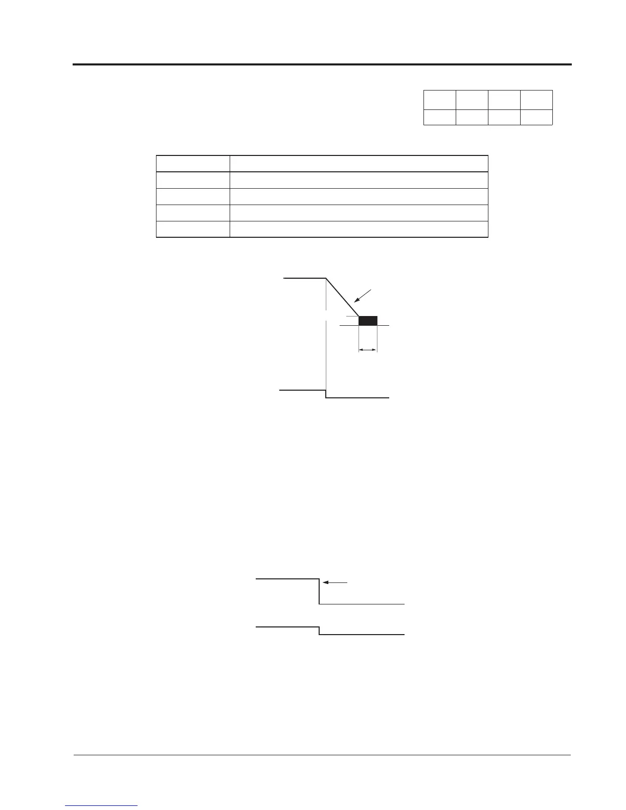
· Deceleration to Stop (B1-03 = “0”)
Upon removal of the FWD (REV) run command, the motor decelerates at a deceleration rate deter-
mined by the time set in deceleration time 1 (C1-02) and DC injection braking is applied immediately
before stop. If the deceleration time is short or the load inertia is large, an overvoltage fault (OV) may
occur during deceleration. In this case, increase the deceleration time or install an optional braking
resistor/unit.
Braking torque: without braking resistor, approx. 20% of motor rated torque
with braking resistor, approx. 150% of motor rated torque
· Coast to Stop (B1-03 = “1”)
Upon removal of the FWD (REV) run command, the motor coasts. After a stop command is given, a
run command can be accepted, but operation does not start until after the minimum baseblock time
(L2-03) elapses.
V/f
Control
V/f
w/ PG
Open Loop
Vector
Flux
Vector
B1-03 Stopping Method Selection Stopping Method
Setting Description
0 Deceleration to stop (factory default)
1 Coast to stop
2 DC injection to stop
3 Coast to stop with timer
Output Frequency
Decel time 1 (C1-02)
Run Command
ON
OFF
DC injection Braking Time
at Stop (B2-04)
Factory Default: 0.5 s
DC Injection Braking Start - B2-01)
Factory Default: 0.5Hz
Zero Speed Level (Frequency at
Figure 19 Stopping Method - Deceleration to Stop
Run command
ON
OFF
Output frequency
Inverter output is shut OFF
when stop command is given.
Figure 20 Stopping Method - Coast to Stop
Chapter 3 - Quick-Start Programming
Programming Menu