78 VG5 Installation & Quick-Start Manual
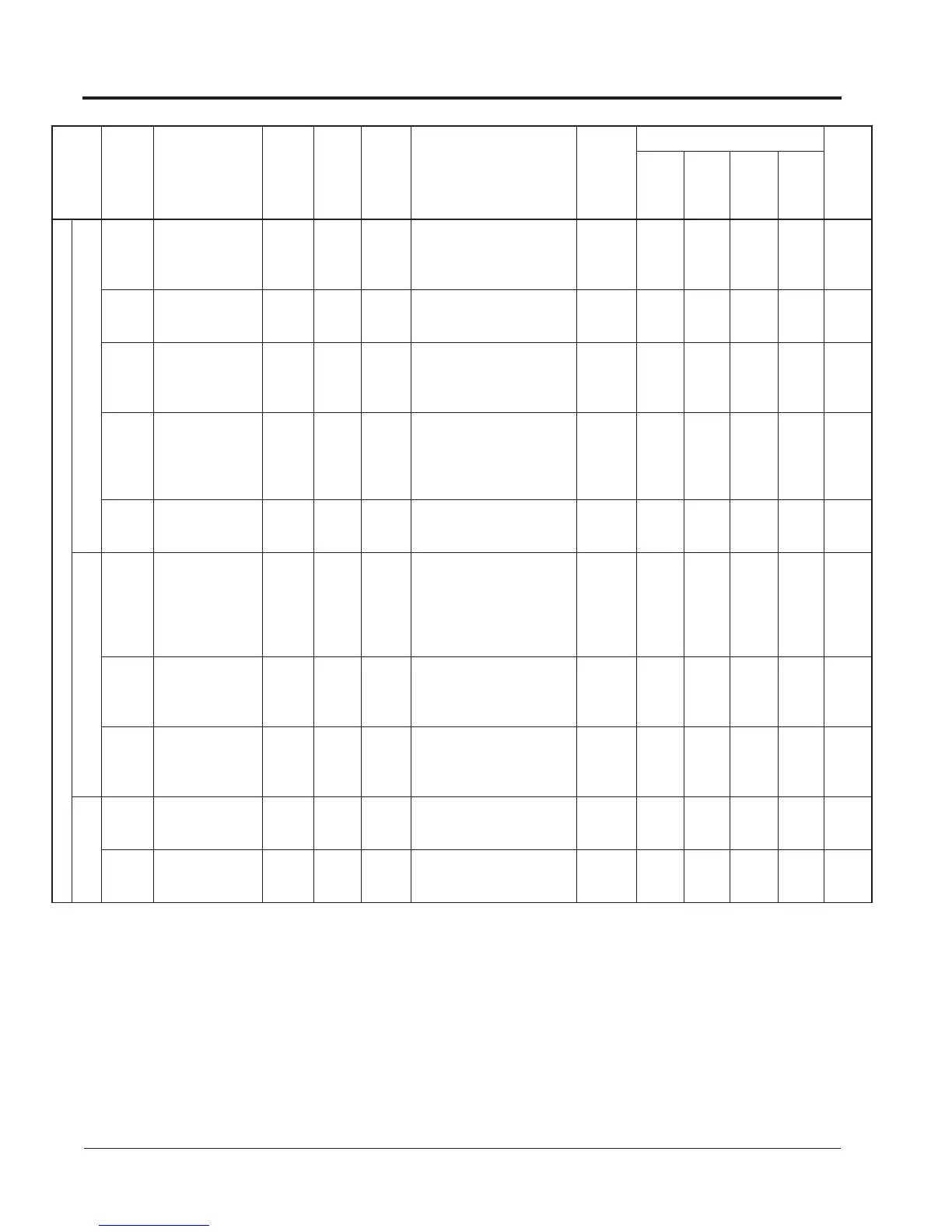
Group b Application
Function b2 DC Injection Brake
B2-01
DC Injection
Braking Starting
Frequency
(DCInj Start Freq)
0.0~
10.0
0.1Hz 0.5 — x B B B B
B2-02
DC Injection
Current
(DCInj Current)
0~100 1% 50 — x B B B -
B2-03
DC Injection Time
at Start
(DCInj Time
@Start)
0.00~
10.00
0.01s 0.00 — x B B B B
B2-04
DC Injection
Braking Time at
Stop
(DCInj Time
@Stop)
0.00~
10.00
0.01s 0.50 *
* When 02-09 = 1 (American),
the setting is 0.00s. <24>
x B B B B
B2-08
<1110>
Magnetic Flux Com-
pensation Capacity
(Field Comp)
0~500 1% 0
100% is no-load current value
at Min. frequency (E1-09)
x - - A A
Speed Search
B3-01
Speed Search
Selection at Start
(SpdSrch at Start)
0,1 1 0*
0: Disabled
1: Enabled
* Factory setting defaults to 0:
Disabled except when (A1-
02=1) (V/F w/PG Fdbk) or 3
(Flux Vector).
x A A A A
B3-02
Speed Search
Operation Current
(SpdSrch Current)
0~200 1% 150*
* Factory setting defaults to 150
when A1-02=0 (V/F Control).
When A1-02=2 (Open Loop
Vector), the default is 100.
x A - A -
B3-03
Speed Search
Deceleration Time
(SpdSrch Dec
Time)
0.1~
10.0
0.1s 2.0 — x A - A -
Delay Timers
Brake Sequence
B4-01
Timer Function
On-delay Time
(Delay-ON Timer)
0.0~
300.0
0.1s 0.0 — x A A A A
B4-02
Timer Function
Off-delay Time
(Delay-OFF Timer)
0.0~
300.0
0.1s 0.0 — x A A A A
Function
Parameter
No.
Name
(Digital Operator
Display)
Setting
Range
Setting
Unit
Factory
Setting
Remarks
(Digital Operator Display)
Change
during
Operation
o: Enabled
x: Disabled
Parameter Access Level
User
Setting
V/f
V/f
w/
PG
Open
Loop
Vector
Flux
Vector
Appendix
VG5 Parameters