SH6- HEATER CONTROLLER SERIES
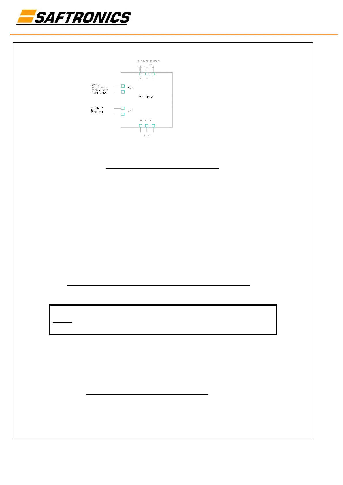
FIG 3.6 - SH6 POWER CONNECTIONS
Figure 3.6 shows a typical power connection diagram. The
input terminals R,S and T are supplied with a 3 phase, fused
supply.
The load is connected to U, V and W.
The FAN input requires a 220V aux supply to be connected to
ensure adequate cooling of the stack. Failure to connect a
FAN supply can cause damage to the drive.
The O/T output is on overtemperature interlock, which must be
wired in series with the STOP circuit.
4. START UP INSTRUCTIONS AND CALIBRATION PROCEDURE
Don't apply power to the system yet!!!
NOTE: Before continuing with this procedure make sure that the
connections are in accordance to an approved system diagram
4.1 SYSTEM SET UP PRIOR TO OPERATION