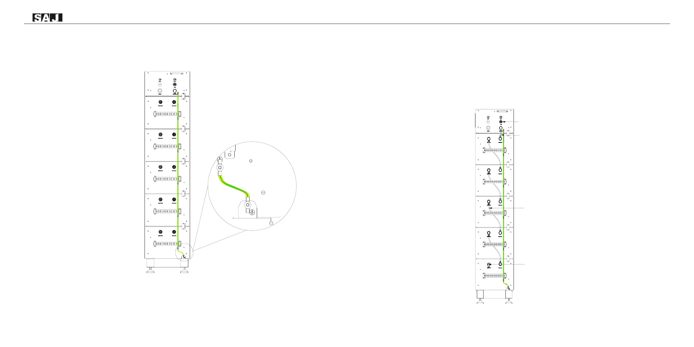
Remove the screw of grounding terminal and secure the additional grounding cable by insert a screw into the
screw hole in the OT/DT terminal. Connect the grounding cables as the following diagram.
Figure 5.2
Connecting the additional
grounding cable
5.2 Connecting Battery COMM Cable
Step1: Connect link port 0 of battery control unit to link port 1 of battery 5 (the battery number can be
varied, it should be depended on the number of battery modules in the system
Step 2: Repeat step 1 to connect the rest of the battery modules
Step 3: Insert a RJ45 plug to link port 0 of battery 1, insert a RJ45 plug to CAN port of battery control unit
Note: If the RJ45 plug is not installed, a communication error will occur.
Figure 5.3
Connecting battery COMM cable
 Loading...