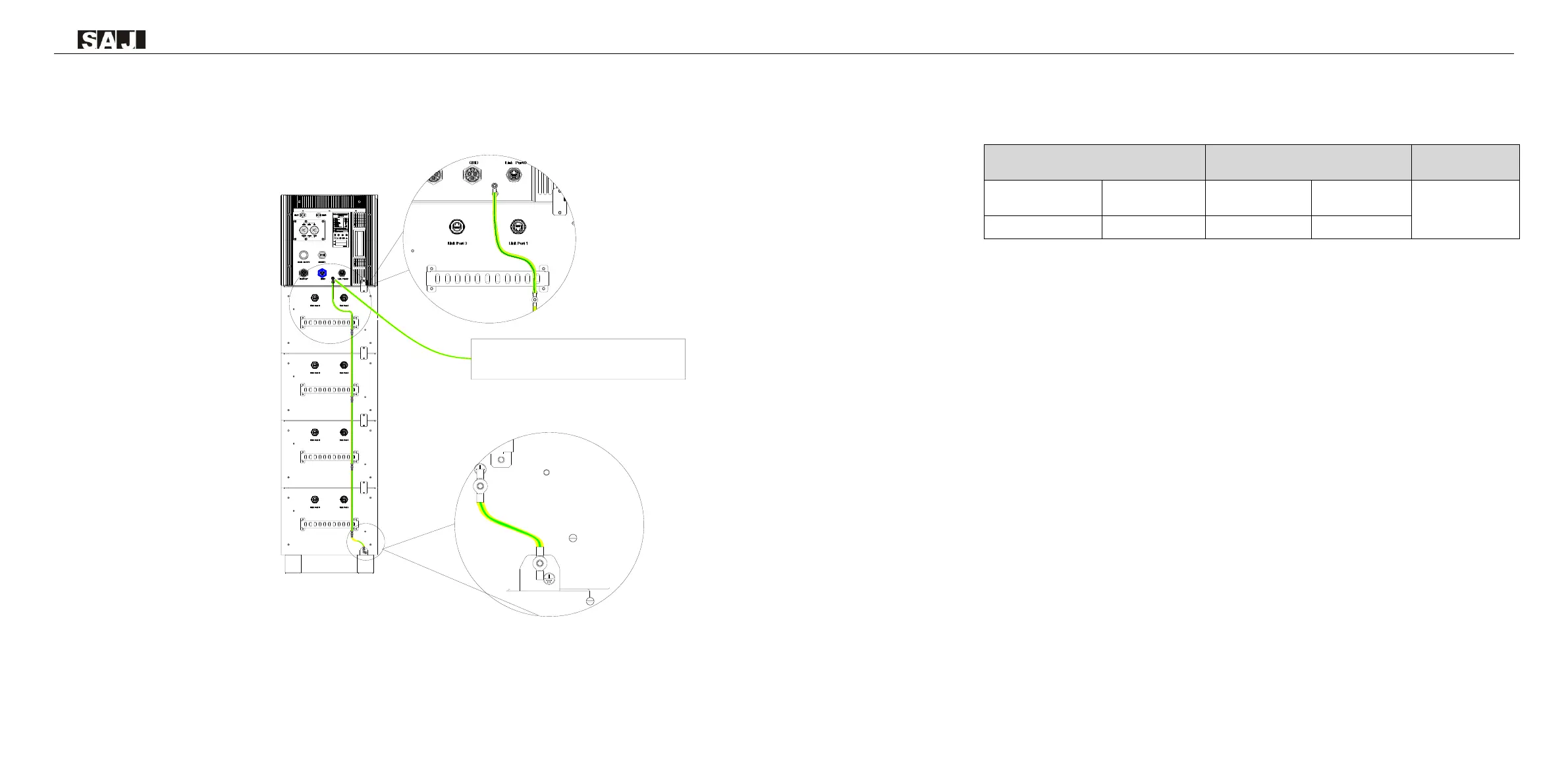
Remove the screw of grounding terminal and secure the additional grounding cable by insert a screw into the
screw hole in the OT/DT terminal. Connect the grounding cables as the following diagram.
Note: A 6-8mm
2
conductor cross-sectional area of cable is recommended for additional grounding cable.
Figure 5.2
Connecting the additional
grounding cable
5.2 AC Grid Wire and Backup Output Connection
Table 5.1
Recommended AC cable specification
Note: If the grid-connection distance is too far, please select an AC cable with larger diameter as per the
actual condition.
Power cable connection procedure:
Step 1&2: Plug in the assembly and disassembly tool to separate the locking nut and cable gland body
Step 3: Pull the assembly and disassembly tool out
Step 4: Unlock the sealing nut
Step 5: Strip the insulation off the wires with 13mm length
Step 6: Thread the cable through the cable gland and secure the wires with spanner
Step 7: Connect the cable to the inverter
Step 8: (Only applicable to market in Australia) During off grid operation time, PE line at the BACK-UP end will
remain to be connected with the PE line at the power grid end inside the inverter.
 Loading...