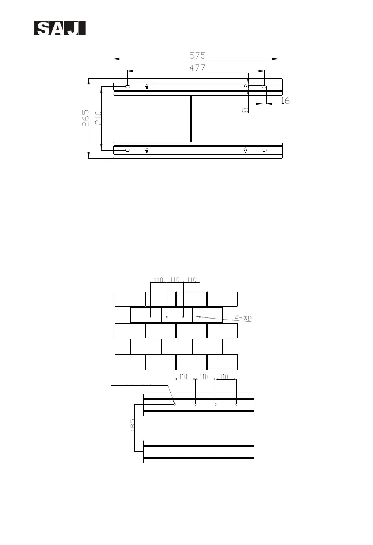
Figure 4.4 Dimensions of rear panel of R6-25K/30K/33K-T3-32, R6-20K-T3-32-LV,
R6-36K/40K/50K-T4-32, R6-25K/30K-T4-32-LV
4.4.2 Drill Holes and Place the Expansion Tubes
According to the guides, drill 4 holes in the wall (in conformity with position marked in
Figure 4.5, Figure 4.6), and then place expansion tubes in the holes using a rubber mallet.
According to the position marked in the figure, drill the corresponding holes and adjust the
position of the bracket so that the inverter is perpendicular to the horizontal plane.
Figure 4.5 Drill holes’ dimensions of R6-15K/17K/20K/22K/25K-T2-32
R6-5K/6K/8K/10K/15K-T2-32-LV
 Loading...