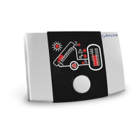
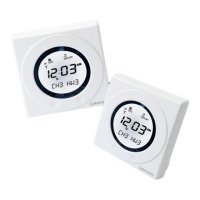
Controller PCSol 150
The SALUS PCSol 150 is an advanced electronic temperature controller designed for efficient heat distribution from solar collectors to a hot utility water reservoir. It manages solar circuit systems based on temperature sensor readings to maximize energy recovery from the collector.
Function Description
The controller operates using a TOUCH&PLAY system, facilitating ease of use with a knob and button. To switch the unit on, the knob must be depressed for three seconds. Upon startup, the controller automatically begins controlling the collector pump. The pump's operation is indicated by an illuminated icon under the pump symbol; when lit, the pump is working, and when unlit, it is not.
The core algorithm of the PCSol 150 involves monitoring temperatures from two sensors: T1 for the solar collector and T2 for the DHW reservoir. When the T1 sensor reaches the minimal collector operation value (TCOLmin), the collector pump is enabled, indicated by an illuminated sun symbol. If the collector temperature drops two degrees below TCOLmin, the sun symbol turns off, and the collector pump is disabled.
The controller initiates heat loading to the reservoir when the temperature difference between the collector (T1) and reservoir (T2) exceeds a user-defined delta value (d4÷14) and TCOLmin is reached. Heat loading continues until the temperature difference falls below dT-2 (current dT is lower than preset by two degrees) or the collector temperature (T1 sensor) drops below TCOLmin-2. The collector pump then turns off. The controller cycles the collector pump on and off based on sunlight intensity and reservoir conditions until the DHW reservoir preset temperature (TsDHW) is reached.
Once TsDHW is reached, the collector pump stops until the reservoir temperature (T2 sensor) drops one degree below TsDHW-1. If conditions allow, the pump will then restart. If the collector pump stops due to TsDHW being reached, the controller continues to monitor T1. If T1 exceeds the critical collector temperature (TCOLcr), the pump will restart to discharge excessive heat from the collector. This forced operation stops when T1 drops 2°C below TCOLcr.
Important Technical Specifications
Measurement Inputs:
- Solar collector temperature (T1, terminals 9 and 10)
- DHW reservoir temperature (T2, terminals 11 and 12)
High-voltage Output:
- DHW pump circuit control CWU P1 (terminals P1L and P1N): 230V/0.5 A
Controller Supply:
- 230 V, I=0.52A*, 50 Hz (*power intake only by controller is 0.02A)
- Nominal impulse voltage: 2500 V~
Operating Conditions:
- Temperature: 0 ≤ Ta ≤ 40 °C
- Humidity: 10-90 %, without condensation
- Protection degree: IP 20
Physical Specifications:
- Weight: ~280 g (controller only)
- Dimensions WxHxL: 140x95x40
Temperature Measurement Accuracy:
- Controller internal structure: Pt1000 class B (CT6 and CT6w)
- Temperature range:
- -40 ÷ 0 °C: ±3 °C
- 0 ÷ 130°C: ±2 °C
- 130 ÷ 210°C: ±3 °C (at ambient temperature of 23°C)
- Displayed range / Step:
- T1: 10 ÷ 200°C with step of 10 K
- T2: 35 ÷ 80°C with step of 5 K
- Measured range / Step:
- T1: -40 ÷ 210°C with step of 0.6 K
- T2: -10 ÷ 110°C with step of 0.5 K
Connectors:
- Spring-loaded terminals for wires with end sleeves.
- Power supply circuits: 0.75÷1mm² (max 1.5mm² for bare wires)
- Low-voltage circuits: 0.25-0.75mm²
- Insulation and sleeve free length for wires: 8÷10mm
Usage Features
Temperature Display: Measured temperatures from both sensors (T1 for collector, T2 for reservoir) are shown on linear display indicators. The number of lit segments increases with temperature. T1 is displayed in 10°C steps, and T2 in 5°C steps.
Screen Navigation: Turning the knob selects the screen position for editing, indicated by a slow blinking cursor. Pressing the knob initiates editing, causing the indicator to blink fast. To exit editing or selection mode, depress the knob for 3 seconds or leave untouched for 10 seconds.
Temperature Presets:
- TsDHW (Temperature setting for DHW reservoir): The target temperature for the DHW reservoir. Set by placing the cursor on the T2 indicator, pressing the knob, and turning it to adjust the value in 5°C steps.
- TCOLmin (Minimal collector temperature): The minimum T1 temperature required for heat loading to the DHW reservoir. Set by moving the cursor to the sun symbol indicator, pressing the knob, and turning it to adjust the value in 10°C steps.
- TCOLcr (Critical collector temperature): The T1 temperature at which the collector pump will operate to discharge excessive heat, even if the reservoir is at its preset temperature. Set by moving the cursor to the T1 indicator, pressing the knob, and turning it to adjust the value in 10°C steps.
Controller Settings (Options): Options are accessed by moving the cursor to the option indicator and pressing the knob. Turning the knob browses options, and pressing it again modifies the selected option. Active options blink fast, inactive ones blink slowly. Values are shown on the left side of the indicator.
- Setting of deltas (d4÷14): Defines the temperature difference (T1-T2) that starts the collector pump. Possible values: 4, 6, 8, 10, 12, 14K.
- Critical temperature alarm (AL): Enables or disables an audible alarm for the critical collector temperature (TCOLcr). Even if the audible alarm is off, the controller will still take action to discharge heat.
- Maximal DHW temperature (Max85÷95): Sets the maximum reservoir temperature (T2) at which the controller will stop heat loading and trigger an overheating alarm. Possible values: 85, 90, 95°C. This alarm has the highest priority and stops collector pump operation, even in critical collector temperature scenarios.
Alarms: The controller signals alarms with an acoustic signal and a blinking alarm indicator. Five alarm situations are recognized:
- T1 sensor malfunction, interruption: Indicates damage or interruption in the T1 sensor circuit. Collector pump stops.
- T1 sensor malfunction, short circuit: Indicates a short circuit in the T1 sensor circuit. Collector pump stops.
- T2 sensor malfunction, interruption: Indicates damage or interruption in the T2 sensor circuit. Collector pump stops.
- T2 sensor malfunction, short circuit: Indicates a short circuit in the T2 sensor circuit. Collector pump stops.
- DHW reservoir overheating: Triggered when T2 reaches the maximal DHW temperature preset. Collector pump stops.
- Collector critical temperature: Triggered when T1 reaches TCOLcr. Allows normal system operation and can be disabled. Collector pump starts unless other alarms are active or the reservoir is not overheated.
- Collector maximal temperature: Triggered if T1 exceeds 180°C. Collector pump stops.
Switching Off: To switch off, depress the knob for about 3 seconds in displaying mode. If in another mode, exit that mode first.
Test of Unit: Upon startup, the unit performs a test, alternately displaying a testing screen and the software version. The testing screen should illuminate all segments evenly. Unlit segments indicate controller damage.
Maintenance Features
Installation: The controller is designed for vertical wall-mounted installation in dry environments with minimal conductive contamination (2nd degree of contamination according to PN-EN 60730-1). It must not be used in water condensation conditions or exposed to water. Installation must be performed by a qualified and authorized technician in accordance with EN 60335-1 standard, with power supply disconnected.
External Circuits Connection: The manual provides detailed diagrams for connecting power supply and temperature sensors. The electrical installation must include a device for disconnecting both supply poles.
Temperature Sensors: Sensors (CT6w for collector, CT6 for reservoir) are Pt1000 type with brass coats. They should be installed close to the measurement point and thermally insulated. The collector sensor (CT6w) requires special high-temperature silica cables and must not be replaced with a standard CT6 sensor due to potential insulation damage at high collector temperatures.
Fuse Replacement: Before replacing the fuse, disconnect the unit from the power supply. The fuse cannot be visually checked but can be tested with an ohmmeter (infinite resistance indicates a burnt fuse). Use a sub-miniature slow blow fuse 1.25A compliant to IEC 60127, with a maximum switching current not lower than 100A (e.g., MXT-250 from Schurter). Open the casing and replace the fuse.
Troubleshooting: The manual includes a troubleshooting table for common issues like the controller not working or collector overheating, providing remedies such as checking power supply, fuse, pump speed, and temperature presets.
Document Keeping: The installation and operating manual, along with other relevant documents, should be kept for future reference and transferred to a new user if the unit is moved or sold.