Do you have a question about the Salus WT100 and is the answer not in the manual?
Provides an overview of the WT100 weather controller and its functions.
Explains the manual structure and responsibilities regarding damages.
Advises on keeping manuals in a safe place for future reference.
Explains the graphical symbols used throughout the manual.
Details the product's compliance with the WEEE directive for electronic waste.
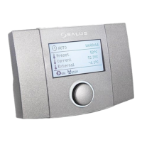
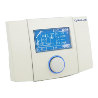
Explains the main display elements and their meaning.
Details how the controller manages heat sources and heating circuits.
Allows switching between OFF, Auto, Comfort, Economy, and Auto-Eco operating modes.
Enables setting time intervals for temperature changes and heat source control.
Manages automatic or manual activation of heating and hot water loading.
Allows adjustment of date, time, screen brightness, contrast, sound, and language.
Provides access to temperature information and enabled devices.
Covers features like supporting heat source or heating circuit independently.
Illustrates a hydraulic scheme with a four-way valve for central heating or floor circuits.
Shows a hydraulic scheme with a three-way valve and hydraulic coupling for central heating.
Depicts a hydraulic scheme for underfloor heating with a three-way valve and hydraulic coupling.
Specifies prohibited environments and acceptable contamination levels for installation.
Details vertical wall mounting, wire routing, and safety requirements.
Covers surface-mounted installation, cable routing, and preventing strain.
Explains the types of sensors, cable extensions, and installation locations.
Details the placement and connection of the external weather sensor.
Provides resistance values for checking sensor accuracy at different temperatures.
Describes connecting a room thermostat and its effect on heating circuit temperature.
Explains how to connect the heat source contact for turning it on and off.
Contains settings for supporting the heating circuit and controlling its operation.
Includes parameters for hysteresis, minimum/maximum temperatures, and buffer functions.
Details support, system type, control methods, and temperature settings for the heating circuit.
Covers settings for heat source support, hysteresis, temperature limits, and buffer options.
Manages return sensor support, frost protection, and cooling functions.
Includes settings for room thermostat, temperature correction, external sensor, manual control, and screed drying.
Lists controller prompts for alarms, damage, and sensor status.
Explains settings for heating circuits with and without weather sensors, including room thermostat integration.
Details the frost protection function, its activation, and temperature-based operation.
Describes how the controller behaves after a power interruption.
Explains the function to cool down the heat source before an overheat alarm.
Protects the pump from immobilization due to scaling via periodic switching.
Provides instructions for replacing the controller's fuse.
The SALUS WT100 is a weather controller designed to manage the temperature in a heating circuit, typically involving a 3- or 4-way valve with a drive-controlled 3-point mechanism. It also supports the connection of an additional circulation pump and can control a heat source via a dry contact. This device is suitable for households, similar premises, and light industry facilities.
The primary function of the WT100 is weather-compensated control, where the heating circuit's preset temperature is determined based on a programmed heating curve and the measured outside temperature. It features automatic detection of heating seasons, can work with a room thermostat, and controls the heat source. The controller also implements return temperature protection to prevent low return water temperatures and offers protection against boiler boiling (for coal boilers) in short-circuit scenarios.
The WT100 is equipped with a timer (clock operation maintained for 48 hours without power) and an intuitive TOUCH&PLAY system for easy operation. Settings are adjusted via a rotary encoder, which can be rotated to increase or decrease values and pressed for selection or approval. A long press (3 seconds) exits a parameter without saving changes. The main menu displays icons representing various functions.
The controller supports several working modes:
The Schedule function allows users to define time intervals for decreasing the preset temperature in the heating circuit or for turning the heat source on/off. This enables automatic temperature adjustments, for example, at night or when rooms are unoccupied, to save energy without compromising comfort. Schedules can be set for each day of the week.
The Summer/Winter function manages automatic or manual heating activation. It also allows for domestic hot water (DHW) container loading in summer without heating the central heating system. If an external temperature sensor is connected, the Summer function can be automated based on specified ON/OFF temperatures.
General settings allow adjustment of date, time, screen brightness, contrast, sound, and language. The Information menu provides access to current temperatures and active devices. Additional functions offer user support, such as controlling the heating circuit independently when the heat source support is turned off, or controlling the heating circuit with mixing and optional thermostat influence.
The manual provides three hydraulic schemes:
| Brand | Salus |
|---|---|
| Model | WT100 |
| Category | Controller |
| Language | English |