14
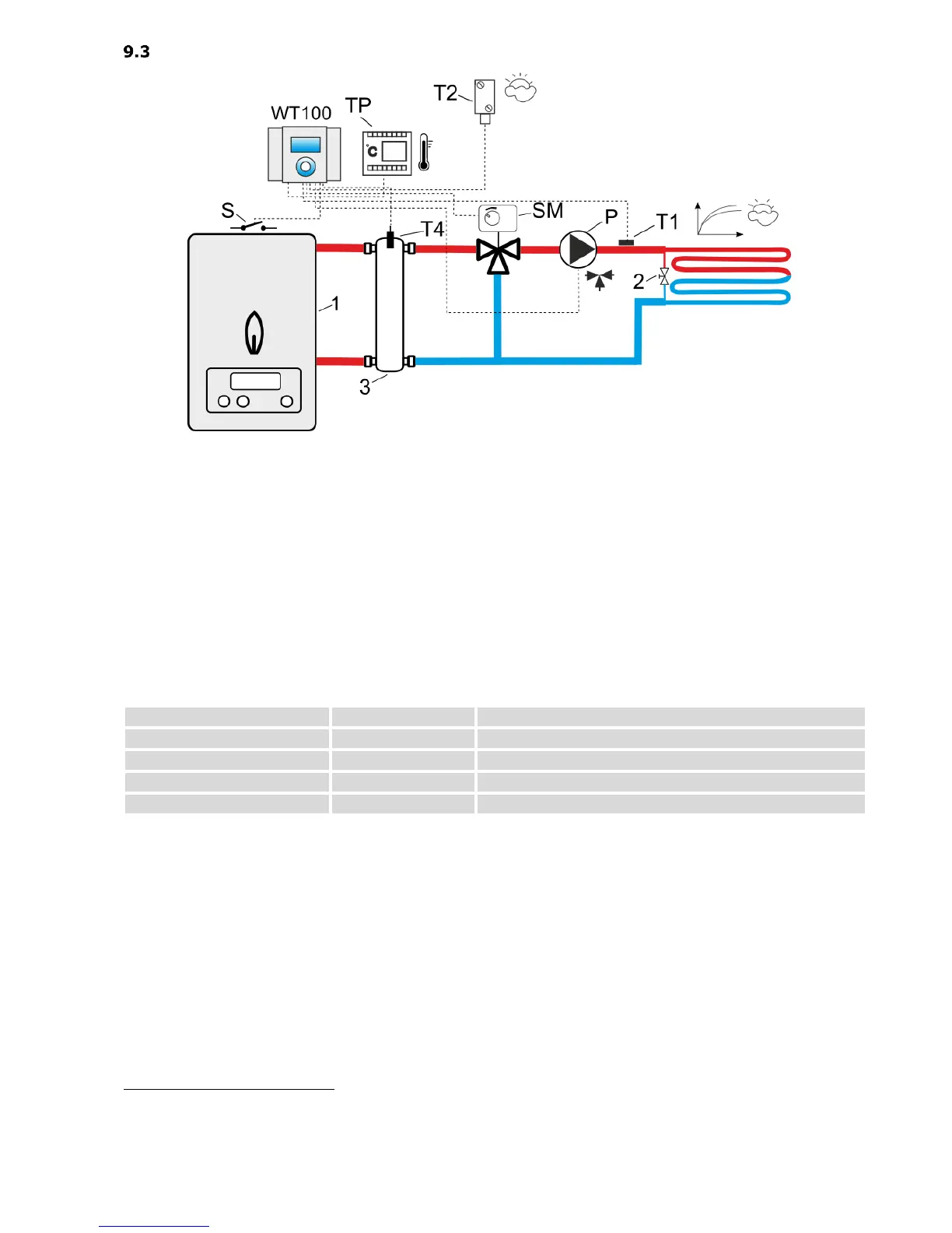
Scheme 3
Hydraulic diagram of the three-way valve controlling circuit underfloor heating (with a hydraulic
coupling)
Legend:
TP – room thermostat (NO-NC)
T1 – heating circuit temperature sensor type CT10
T2 – external temperature sensor (weather) type CT6-P
T4 – hydraulic coupling temperature sensor type CT10
P – pump heating circuit
SM – three-way valve + actuator
1 – heat source with (S) ON-OFF contact (gas- or oil- boiler)
2 – relief valve different pressure
3 – hydraulic coupling.
RECOMMENDED SETTINGS:
Service settings Kind of the system
Service settings Heating circuit
Service settings Room thermostat
Service settings Heating circuit
The presented hydraulic diagram does not replace central heating engineering design and may be used for
information purposes only!