solar collector temperature (T1, terminals 9 and 10)
d.h.w. reservoir temperature (T2, terminals 11 and 12)
DHW pump circuit control CWU P1(terminals P1L and P1N):
230V/0.5 A
0 ≤ Ta ≤ 40 °C, humidity 10-90 %, without condensation
* power intake only by controller is 0.02A
Table of temperature measurement accuracy:
Controller internal structure
Pt1000 class B (CT6 and CT6w)
10 ÷ 200°C with step of 10 K
35 ÷ 80°C with step of 5 K
-40 ÷ 210°C with step of 0,6 K
-10 ÷ 110°C with step of 0,5 K
* unit at ambient temperature of 23°C
10.1. Elements of the set
- Controller PCSol 150
- Temperature sensor T1(CT6w)
- Temperature sensor T2(CT6)
- Installation and operating manual
11. INSTALLATION
The controller is designed for operation in the
environment where only dry conductive
contaminations may be present (2 degree of
contamination according to PN-EN 60730-1).
In addition, the controller may not be used in
water condensation conditions and it may not be
exposed to water.
The unit software does not ensure
required protection level that must be
assured by external protections of the
system.
11.1. Installation of the controller
The controller is designed for vertical wall-
mounted installation. Mounting hole locations are
presented in Fig. 15.1 External wires are supposed
to be leaded out of the wall (flushed).
Before opening the unit casing,
disconnect power supply. The unit
installation must be done at disconnected
voltage.
Controller must be installed by qualified
and authorized technichian in accordance
with EN 60335-1 standard.
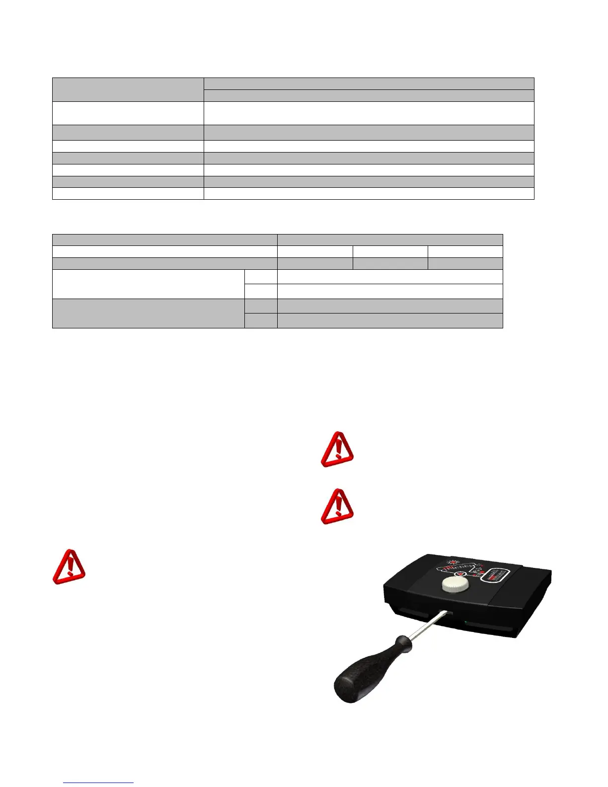
Fig. 11.1 shows how to open the panel
Fig. 11.1 How to open casing panel