8
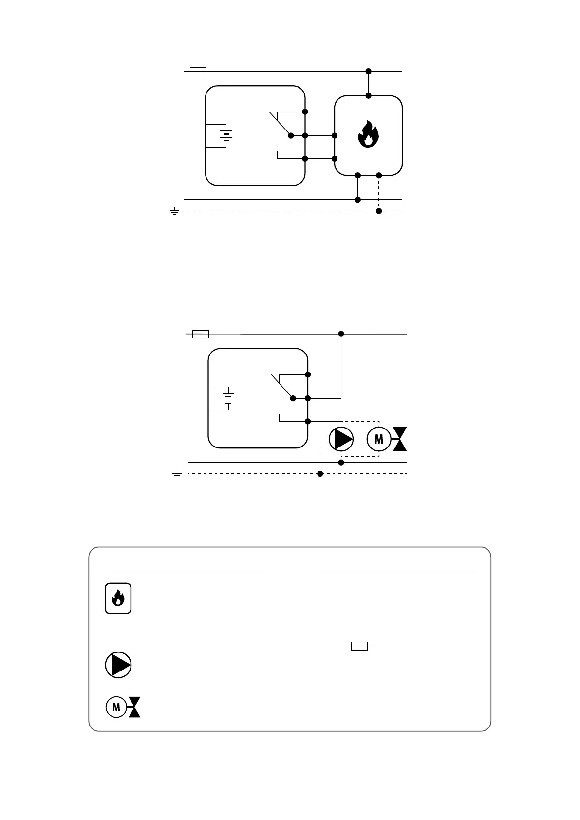
3. Connection description
L
COM
NO
NC
N
L
N
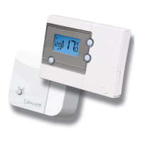
RT310
PODŁĄCZENIE KOTŁA *
3V
2 x AA
L
N
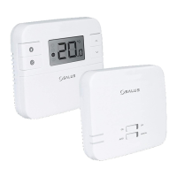
RT310
MAX
3 (1) A
PODŁĄCZENIE KOTŁA *
3V
2 x AA
3V
2 x AA
COM
NO
NC
BOILER CONNECTION*
or
L, N - power supply 230V
NO, COM, NC - voltage-free output
- fuse
Legend: Symbols explanation:
Pump
Valve actuator
Boiler - Boiler connection*
- Boiler’s contacts for ON/OFF
thermostat (according to the
boiler’s instructions)