4 | SAMLEX AMERICA INC.
EVO INVERTER/CHARGER | Quick Start Guide
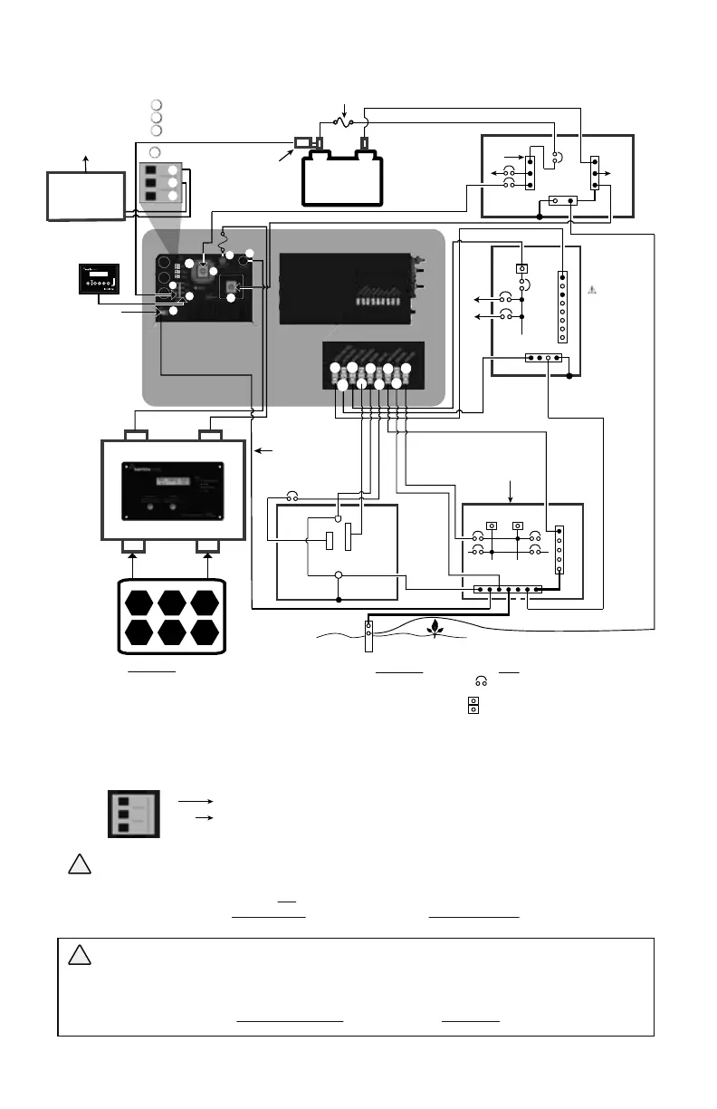
Fig 1 Typical Shore Based Installation
Optional
Generator Auto
Start/Stop Control
Module
BATTERY
TEMPERATURE
SENSOR MODEL
EVO-BCTS
+
-
LEAD ACID
BATTERY BANK
NO - Normally Open Contact
Common
NC - Normally Closed Contact
BATTERY SIDE FUSE (Within 7” of Positive Post)
EVO INVERTER
CHARGER
Ground
Terminal (5)
External
Charge
Controller
Solar Panel(s)
Battery -
Battery +
PV -
PV +
Fuse
G-B
N-B
ELECTRICAL
SUB- PANEL
FOR EVO
( CAUTION!
Use 120 VAC
Single Phase
Panel and NOT
120/240VA
Split Phase
Panel)
N
To
Loads
Optional
Remote Control
EVO-RC
Ground Rod embedded in earth.
GE
N
PANEL
GENERATOR
(See Caution!)
G-B
A B
SBJ
N-B
SERVICE
PANEL
AC SIDE
(See Fig 2.3)
G
FRONT
(See Fig 2.1)
1.
2.
3.
4.
5.
6.
7.
14.
4.
5.
6.
7.
8.
9.
10.
11.
12.
AC SIDE OF EVO
GRID LINE
GRID GND
GRID NEUTRAL
GEN LINE
GEN GND
GEN NEUTRAL
OUTPUT LINE
OUTPUT GND
OUTPUT NEUTRAL
A
B
N-B
SBJ
G-B
GE
GEC
E
N
L
G
OTHER
Circuit breaker
120 VAC Leg A
120 VAC Leg B
(Legs A&B are split phases)
Neutral Bus Bar
System Bonding Jumper
Grounded Bus Bar
Grounding Electrode (Ground Rod)
Grounding Electrode Conductor
Earth Connector on generator
(bonded to frame/chassis of the generator)
Neutral terminal of generator output
Line terminal of generator output
Grounding terminal of generator output
LINE
To Remote Start/Stop
Terminals on the
Generator
12
11
5
7
6
1
3
4
10
8
4
5
7
9
6
14
Status Relay
NO
Common
NC
To optional
Generator Auto
Start/Stop
Module
14
A
B
C
A
B
C
2
DC SIDE OF EVO
Battery Positive
Battery Negative
External Charger Positive
External Charger Negative
Grounding Terminal
RF-45 Jack for Temperature Sensor
RJ-45 Jack for Optional Remote Control EVO-RC
Status Relay Terminals for initiating automatic generator start/stop
GRID ELECTRICAL
PANEL (120/240VAC),
SPLIT PANEL
Minimum Wire
Size AWG #6
E
L
Pos (+)
Bus
Neg (-) Bus
G-B
DC ELECTRICAL
PANEL
CAUTIONS!
1. When both the Grid and Generator are connected to the EVO
TM
simultaneously as shown in this Fig 3.14, please ensure that:
(i) The generator chassis / frame is grounded to the Earth Ground through Ground Rod of the Grid Electrical Panel and
(ii) The Neutral conductor of the generator is NOT bonded to the chassis / frame of the generator. Please refer to Section 3.14.2.1 for details.
2. If only Generator is connected (no Grid connection), the Neutral of the Generator SHOULD BE BONDED to its metal frame. Please refer
to Section 3.14.2.2
ATTENTION!
1. Lorsque le réseau et le générateur sont connectés simultanément à l'EVO, comme indiqué sur la gure 3.14, veuillez vous assurer que :
(i) Le générateur / châssis châssis est relié à la masse de la Terre par l'intermédiaire de tige de mise à la terre du panneau électrique et grille
(ii) le conducteur neutre de la génératrice n'est pas collé sur le châssis / cadre de la génératrice. Veuillez vous reporter à la section 3.14.2.1 pour
plus de détails.
2. Si seul le générateur est connecté (pas de connexion au réseau), le neutre du générateur DOIT ÊTRE LIÉ à son cadre métallique.
Veuillez vous référer à la section 3.14.2.2
!
!
GEC
GEC
GEC