2
840801 R. 03/18
SAMOA Industrial, S.A. · Pol. Ind. Porceyo, I-14 · Camino del Fontán, 831 · 33392 - Gijón - Spain · Tel.: +34 985 381 488 · www.samoaindustrial.com
2018_03_15-12:00
EN
TYPICAL INSTALLATION
STATIONARY INSTALLATION See figure 3 for a typical installation with all the recommended
accessories for the pump to operate correctly.
NOTE: The compressed air supply must be fixed between 3 and 10 bar
(40 – 140 psi), being 6 bar (90 psi) the recommended pressure. An air
closing valve must be installed, in order to be able to close the
compressed air line at the end of the day. (If the air inlet not is closed
and there is a leakage in some point of the grease outlet circuit, the
pump will start automatically, emptying the container).
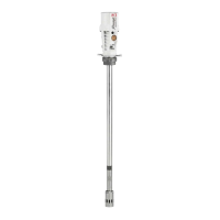
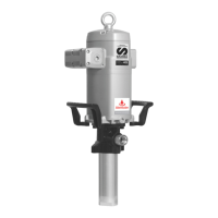
DESCRIPTION
Compressed air operated piston reciprocating pumps designed for high
pressure greasing. These pumps are compatible with all types of mineral
greases (up to NLGI-2 viscosity). These pumps can be supplied as
separate components or as complete systems with all the elements
necessary for its installation. These pumps can be mounted on mobile
units as well as on fixed drums, connected to a distribution line.
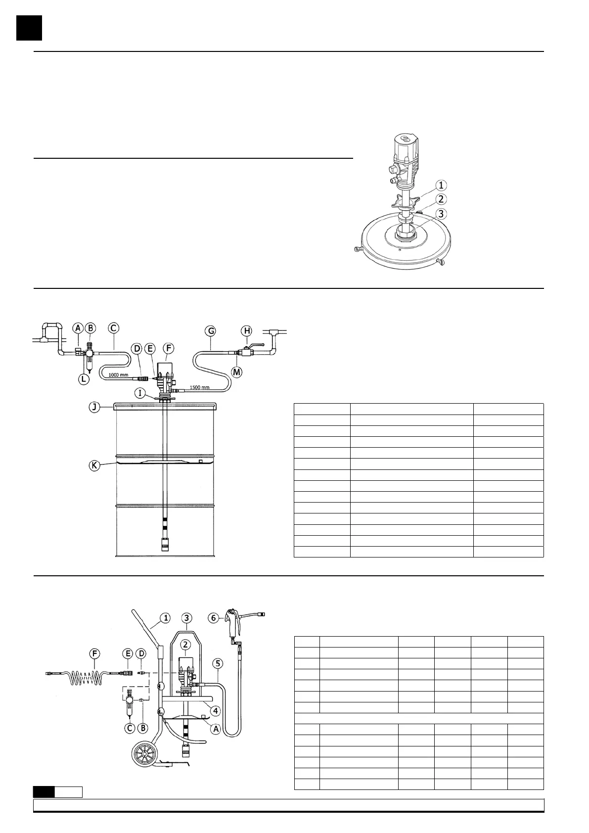
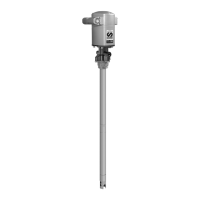
INSTALLATION
These pumps must be mounted on drums using covers fitted with a 2”
bung. Loose the star nut (1) of the bung adaptor to remove the inferior
nut (3), and screw this into the 2” bung opening of the cover. Place the
star nut (1) and the three jaws (2) on the suction tube. Introduce the
pump through the opening and fasten the assemble at the desired
height (fig 2).
Fasten the cover to the drum.
Fig. 2
Pos Description Part No.
A Air closing valve 950319
B Filter regulator 240500
C Air hose 246010
D Quick coupling 253114
E Connection nipple 259014
F 55:1 Pump PM3 409200
G Grease hose 412190
H Grease closing valve 950304
I Bung adaptor 410000
J Cover (185 kg drum) 418006
K Follower plate 417004
L Nipple 239005
M Nipple 945516
424170 (no trolley)
424172 (no trolley)
424150 (with trolley)
424152 (with trolley)
Numbers (1,2,…etc) included, letters (A,B,…etc) optional.
Pos Description 424170 424172 424150 424152
1 Drum trolley - - 430000 430000
2 Grease pump 404100 404100 404100 404100
3 Carrying handle 741603 741602 741603 741603
4 Drum cover 418013 418002 418013 418002
5 Outlet hose 412102 412102 412102 412102
6 Grease gun 413080 413080 413080 413080
Optional
A Follower disc 417006 417001 417006 417001
B Nipple 239000 239000 239000 239000
C Filter regulator 240500 240500 240500 240500
D Connection nipple 259014 259014 259014 259014
E Quick coupling 253114 253114 253114 253114
F Air hose 243105 243105 243105 243105
MOBILE UNITS
Fig. 3
Fig. 4