EB 2512 EN 33
Start-up and operation
6.1.1 Installing the regulator
Î RefertoFig.3
1. Close the shut-off valves upstream and
downstream of the regulator while the
regulator is being installed.
2. Remove the protective caps from the
valve ports before installing the valve.
3. Lift the valve using suitable lifting equip-
ment to the site of installation. Observe
theowdirectionthroughthevalve.The
arrow on the valve indicates the direction
ofow.
4. Makesurethatthecorrectangegaskets
are used.
5. Bolt the pipe to the valve free of stress.
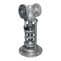
6. Mount the actuator.
− Diaphragm actuator DN15 to 100
Insert the actuator stem (11) through the
hole in the crossbeam (8) into the travel
stop cap with cotter pin (20) and fasten
the actuator with the nuts (9). Observe
thetighteningtorquesspeciedinsec-
tion7.5.
− Bellows actuator DN15 to 50
Remove the crossbeam (8) from the
valve.
Insert the actuator stem (11) into the
travel stop cap with cotter pin (20).
Align pillars (8.1) and fasten the actuator
with the nuts (8.2). Observe the
tighteningtorquesspeciedin
section7.5.
− Bellows actuator DN65 to 100
Remove the crossbeam (8) from the
valve.
Unscrew the pillars (8.1).
Screw the pillars (8.1) into the threaded
holes(8.3)oftheactuatorangeasfar
as they will go.
Insert the actuator stem (11) into the
travel stop cap with cotter pin (20).
Fasten the pillars (8.1) with the nuts (8.2)
ontothevalveange.Observethetight-
eningtorquesspeciedinsection7.5.
7. Lock the cotter pin (20) on the travel stop
cap.
8. Mount the control line (17) onto the valve
and actuator. Observe the tightening
torquesspeciedinsection7.5.
− With diaphragm actuators
For steam or liquids above 150°C
installthecompensationchamberandll
it with the process medium. Observe the
tighteningtorquesspeciedin
section7.5.
9. Slowly open the shut-off valves in the
pipeline after the valve has been in-
stalled.

 Loading...