EB 8052-E EN 5-1
Installation
5 Installation
The work described in this section is only to
be performed by personnel appropriately
qualied to carry out such tasks.
5.1 Installation conditions
Work position
The work position for the control valve is the
front view looking onto the operating con-
trols (including valve accessories).
Plant operators must ensure that, after instal-
lation of the device, the operating personnel
can perform all necessary work safely and
easily access the device from the work posi-
tion.
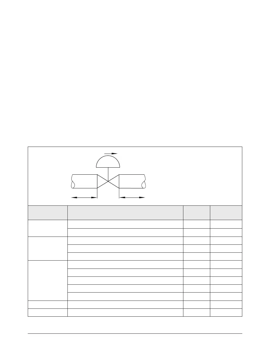
Pipeline routing
The inlet and outlet lengths (see Table 5-1)
vary depending on several variables and
process conditions and are intended as
recommendations. Contact SAMSON if the
lengths are signicantly shorter than the
recommended lengths.
Table 5-1: Inlet and outlet lengths
a x NPS b x NPS
State of process
medium
Valve conditions
Inlet length
a
Outlet length
b
Gas
Ma≤0.3 2 4
0.3≤Ma≤0.7 2 10
Vapor
Ma≤0.3
1)
2 4
0.3≤Ma≤0.7
1)
2 10
Saturated steam (percentage of condensate >5%) 2 20
Liquid
Free of cavitation/w<10m/s 2 4
Cavitation producing noise/w≤3m/s 2 4
Cavitation producing noise/3<w<5m/s 2 10
Critical cavitation/w≤3m/s 2 10
Critical cavitation/3<w<5m/s 2 20
Flashing – 2 20
Multi-phase – 10 20
1)
No saturated steam
Q Flow rate
a Inlet length
b Outlet length