9-26 EB 8052-E EN
Servicing and conversion
15. LLF20 packing: insert packing follower
(8).
Standard and HT packing: screw in
threaded bushing (8).
16. Place yoke (60) on the valve bonnet (2)
and fasten using the castellated nut (92).
17. LLF20 packing:
− Place packing gland (162) over the
studs (164) on the valve body (2) on-
to the packing follower (8).
− Screw the two spring loading assem-
blies (163) onto the studs (164) and
guide them through the holes on the
packing gland.
Standard and HT packing: continue as
described in step18.
18. Adjust the packing (see information un-
der 'Adjusting the packing' in the 'Instal-
lation' section > 'Testing the installed
valve' > 'Leak test').
19. Loosely thread lock nut (10) and stem
connector nut (9) onto the piston stem
(5.1).
Valve version with anti-rotation xture
11. Continue as described in steps 11 to 18
of the previously described procedure
‘Valve version without anti-rotation x-
ture’ on page9-25.
12. Apply a thin lm of lubricant (114) to the
threads of the stem (9) and screws (303).
Impaired functioning due to incorrectly ap-
plied lubricant.
Î Do not apply any lubricant to the threads
of the clamps (301) or the plug stem.
13. Position the clamps (301) and stem (9)
on the piston stem according to the
'Mounting dimensions' table in the 'In-
stallation' section (under 'Mounting the
external anti-rotation xture') and tighten
screws (303) and washers (304) by
hand.
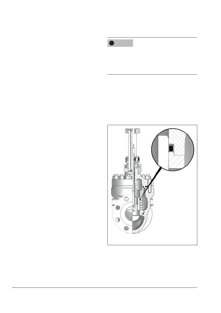
Alignment of the
gasket
Flow to Open (FTO)
Fig.9-7: Alignment of the gasket (45)
NOTICE
!