7-10 EB 3018 EN
Operation
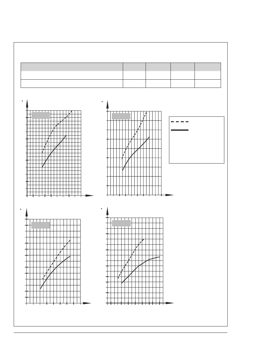
Table 7-3: Flow rate set point ranges for water · Type2423E Regulator, balanced by
a bellows
Set point ranges in m³/h with ... DN125 DN150 DN200 DN250
Diff. pressure at the restriction Δprestriction=0.2bar 40 to 80 50 to 120 70 to 180 90 to 220
Diff. pressure at the restriction Δprestriction=0.5bar 60 to 120 75 to 180 100 to 260 120 to 300
Adjustment diagrams for water
0
082641214161810
80
140
20
120
180
60
40
160
100
25
75
50
[ m³/h ]
[ m
³/h ]
8264121410 16
DN 150
DN 200
U
U
U
DN 250
V
V
[ m
³/h ]
V
25
50
75
100
125
150
175
200
225
250
275
300
325
350
375
400
082641214161810
80
10
70
20
50
30
60
40
90
100
110
120
[ m
³/h ]
DN 125
V
Δp
restriction
=0.5 bar
Δp
restriction
=0.2 bar
V Flow rate
U
Scale divisions of the
set point adjuster
(restriction)
Fig.7-4: Adjustment diagrams for Type2423E Regulator, balanced by a bellows, DN125 to 250