3-2 EB 8015 EN
Design and principle of operation
1
5
4
16
11
84
8
9
10
14
2
17
92
A
2
84
10
9
8
16
11
A8
A7
14
17
1
4
5
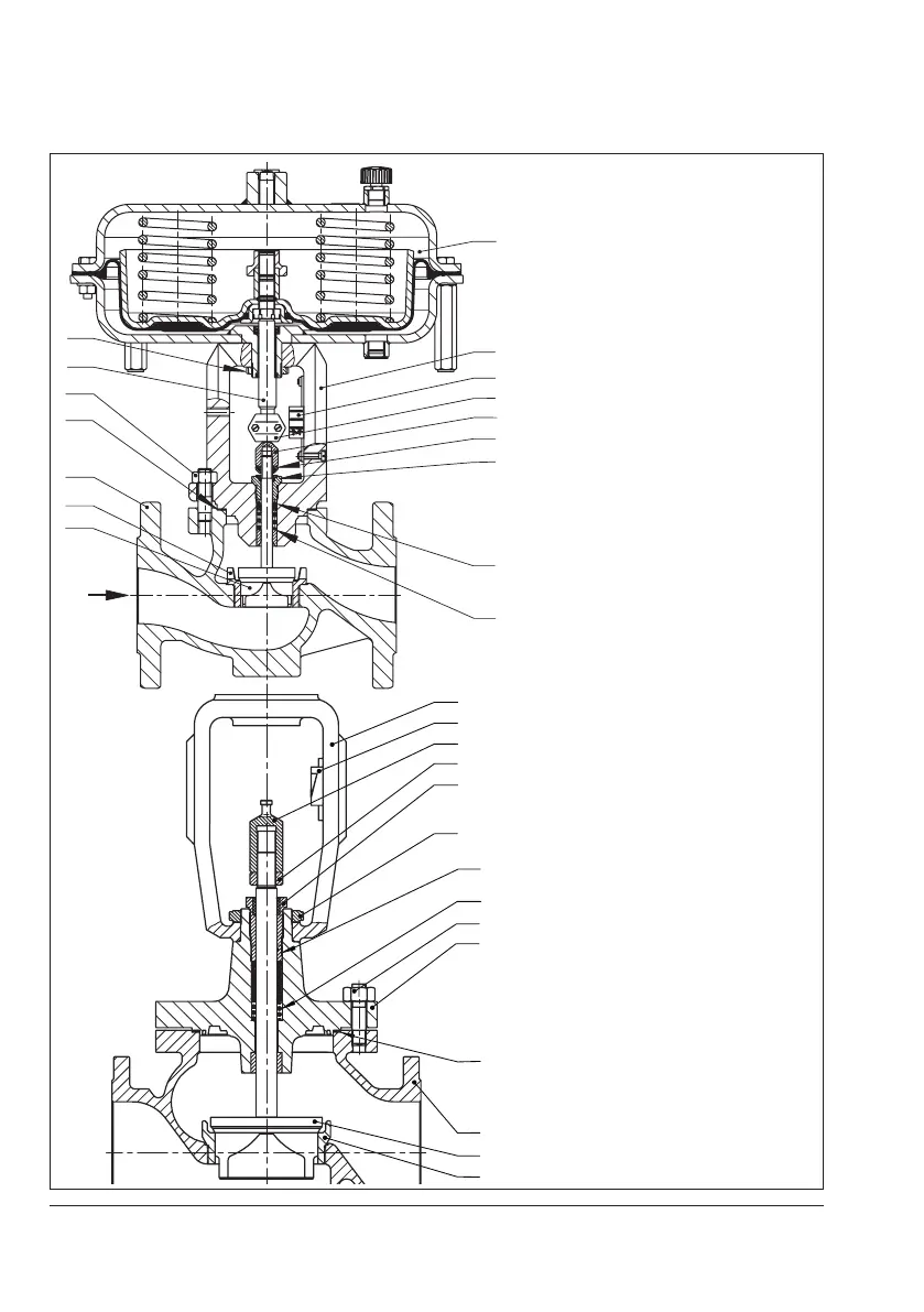
1 Body
2 Flange
3 Yoke
4 Seat
5 Plug (with plug stem)
8 Threaded bushing (packing nut)
9 Stem connector nut
10 Lock nut
11 Spring
14 Nuts
16 Packing
17 Body gasket
84 Travel indicator scale
92 Castellated nut
A Actuator
A7 Actuator stem
A8 Ring nut
A26 Stem connector clamps
Fig.3-1: Type3241-1 Control Valve with
Type3271 Pneumatic Actuator,
body up to DN150
Fig.3-2: Type3241 Valve, body
DN200 to 300