In a live sound application, the 1/2 bus outputs are con-
nected to a power amplifier or powered speakers. In a
recording application, the
nect a stereo device such as computer sound card, DAT,
In a live sound application, the 3/4 bus outputs are con-
nected to a power amplifier or powered speakers. In a
recording application, the 3/4 outputs are used to con-
nect a stereo device such as computer sound card, DAT,
The Aux RET 1 LEFT/RIGHT are stereo inputs that are generally used to connect the outputs of an effects processor, but can
also accept the signal from any line level source like a keyboard, recorder and even another mixer. The signal connected to the
Aux RET 1 LEFT/RIGHT will feed the main LEFT/RIGHT MIX bus. The overall level is controlled by the Aux RETURN 1 knob located
in the master section on the front panel
The Aux RET 2 LEFT/RIGHT are stereo inputs that are generally used to connect the outputs of an effects processor, but can
also accept the signal from any line level source like a keyboard, recorder and even another mixer. The signal connected to the
Aux RET 2 LEFT/RIGHT will feed the main LEFT/RIGHT MIX bus. The overall level is controlled by the Aux RETURN 2 knob located
in the master section on the front panel
The Left and Right Mix outputs are summed together and sent to the MONO output. The level of the Mono signal can be
adjusted using the MONO OUT level control located just below the connector and used to feed a speaker zone in a fixed instal-
In a live sound application the LEFT/ RIGHT MIX outputs are connected to a power amplifier or powered speakers. In a record-
ing application, the LEFT/ RIGHT MIX outputs are used to connect a stereo device such as computer sound card, DAT, or cas-
The signal present at the AUX 1 output is sent from the AUX 1 bus, which is fed from the AUX 1 send on the input channels. The
AUX 1 output can be used as the MONITOR MIX bus in a live sound situation by connecting the output to a power amp and
The AUX 2 output is used to send a signal to an external signal processor such as a delay or reverb. The signal present at the
AUX 2 output is sent from the AUX2/DSP bus, which is fed from the AUX2/DSP send on the input channels.
The Control Room outputs are used to connect a studio monitor system. The Control Room outputs have the same output as
the L/R MIX, however, the level can be adjusted independently from the main mix using the C ROOM/HEADPHONES control.
Send and return patch point on TRS (TIP/RING/SLEEVE) jack for interfacing external effects processors on bus 1/2.
Send and return patch point on TRS (TIP/RING/SLEEVE) jack for interfacing external effects processors on bus 3/4.
INSERT- Left and Right Mix Bus
Send and return patch point on TRS (TIP/RING/SLEEVE) jack for interfacing external effects processors onLeft and Right MIX bus.
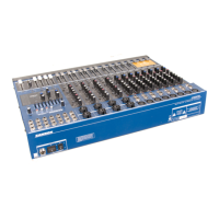
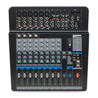
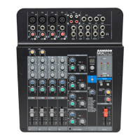
MDR16 Input and Output Connections
The MDR16 features several output connectors allowing you to interface a variety of external devices. A stereo recording device such
as a cassette recorder can be connected to the 2 Track jacks, and power amplifiers can be connected to the CONTROL ROOM and
6
7
8
9
10
11
12
13
14
15
16
17