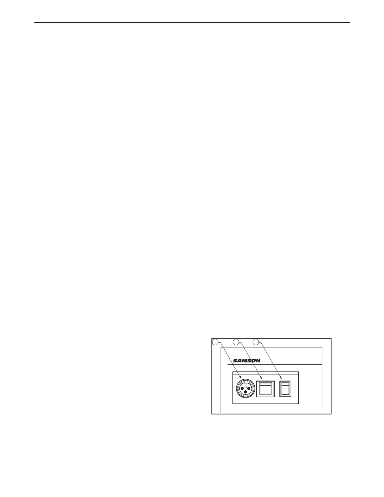
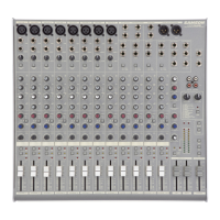
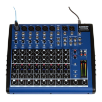
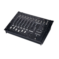
Front and Rear Panel Layout
– Connect External AC power
AC ADAPTER INLET – Connect External AC power AC ADAPTER INLET
– Switches on the MDR16’s main power.
– Engages the 48-Volt Phantom
power supply to microphone pre-amps.
– The Left and Right main Mix outputs are
summed together to a monaural signal and sent out this
– When pressed in, the Amber LED will illu-
minate indicating that the Graphic Equalizer is active.
This control knob is used to adjust
the level of the signal connected to the AUX RETURN 2
When pressed in, the onboard Graphic
Equalizer is switched from the main mix to the AUX 1
Back-lit LED switch used to
assign the AUX RETURN 2 bus to the SOLO bus.
– Indicates that the 48 Volt
– Indicates the MDR16 is powered up.
– Indicates SOLO is selected.
– Indicates the SOLO is in PFL (Pre-Fader Level)
– Twelve-segment display with VU bal-
listics indicates main Mix level.
This control knob is used to adjust the level
of the internal DSP effect in the AUX 1 outputs
This push switch is used to engage the
– Used to switch between the 8
pre-sets of the internal DSP effects processor.
– Back-lit LED switch used to
assign the 3/4 Bus to the SOLO bus.
– Used to change the operating mode
of the SOLO bus from SOLO to PFL (Pre Fader Listen).
– When engaged, the LED lights and
the input channels which are assigned to 3/4 will be
mixed together with the Main Left and Right Outputs.
– When the switch pressed, the red
LED lights indicating the Main Left and Right outputs are
– This global control, back-lit
switch is used to disconnect all channels from the SOLO
- Used to control the overall volume of
the Left and Right main Mix outputs.
– Connect stereo headphones here.
62 HEADPHONE JACK – Connect stereo headphones here. 62 HEADPHONE JACK
– Adjusts the volume of the
control room speakers or headphones.
– A rotary control knob used to set the
overall volume of the SOLO bus.
– Switches between the main Mix and the 2
Track in the Control Room output.
– Used to control the overall volume
– Used to control the overall volume
– Used to control the overall volume
– Used to control the overall volume
– When engaged, the LED lights and the
input channels which are assigned to 1/2 will be mixed
together with the Main Left and Right Outputs.
– Back-lit LED switch used to assign the
This control knob is used to adjust the
level of the internal DSP effect in the Bus 3/4 out-
– Back-lit LED switch used to
assign the AUX RETURN 1 to the SOLO bus.
This control knob is used to adjust the
level of the internal DSP effect in the Bus 1/2 out-
– LED light illuminates when the signal
sent to the internal DSP is clipped.
– Used to mix in level of the
external effects connected to the Aux RETURN 1 inputs.
– LED, back-lit switch used to assign the
channel to the 3/4 output bus.
used to assign the channel to the1/2 output bus.
SOLO Switch (Stereo Channels)
used to assign the channel to the SOLO bus.