USING THE CHANNEL INSERT JACKS
To further control your signal, channels 1-8 on the MDR16 feature an insertion point, or “effects loop”, on one 1/4-inch
phone jack, INSERT SEND and RETURN. An insertion point is a patch-point that interrupts the signal, allowing you to bring
that signal outside to be processed by another device. You can use these connections to interface an external signal pro-
cessor like an equalizer, compressor, noise gate, reverb and other audio devices. A common application for the
insert point is using a compressor.
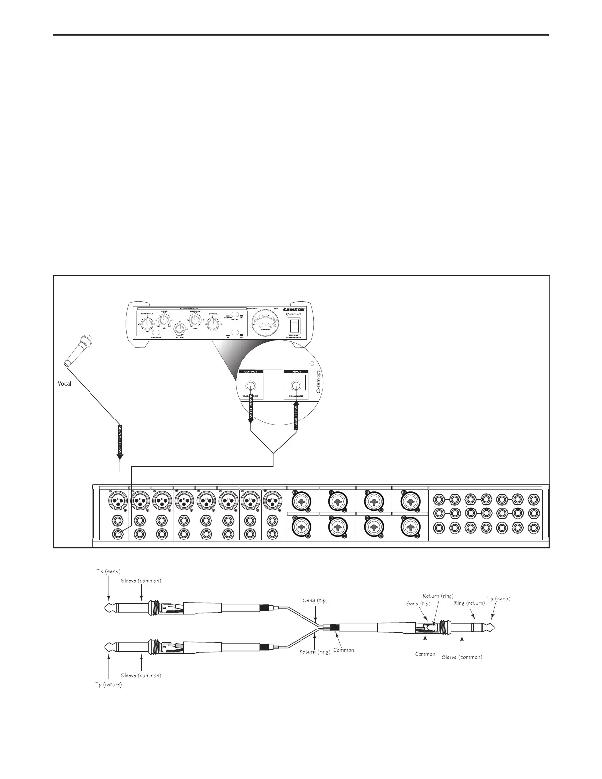
To send a signal to an external processor, use a standard 1/4-inch “Y” insert cable to connect the
point. Connect the TRS (TIP / RING / SLEEVE) plug to the channel INSERT point, and then connect the 1/4-inch (TIP /
SLEEVE), INSERT SEND plug to the input of the external processor. The signal is sent back to the
(TIP / SLEEVE), INSERT RETURN plug connecting to the output of the external processor.
The diagram below shows a typical application for using a compressor (in this example a Samson C com opti) in the
insertion point. Also below, is a diagram showing the wire for the TRS ‘Y” Insert cable.
Insert "Y" Send and Return Cable Wiring Guide