1 GATE OPEN & CLOSED LED - Indicates when
the gate is open or closed.
2 GAIN REDUCTION METER - Displays the
amount of Gain Reduction when Compressor
circuit is activated.
3 INPUT/OUTPUT METER - Displays the Input
or Output signal level based on the settings of
the I/O meter switch.
4 DE-ESSER METER - Displays the amount of
De-Esser effect.
5 LIMITER METER - Display light indicates
when LIMITER circuit is engaged.
6 STEREO LINK SWITCH- When engaged
Channel 2 functions are controlled by the set-
tings on Channel 1.
7 CHANNEL 2 CONTROLS - The same knob and
switch complement as Channel 1 .
Controls and Functions
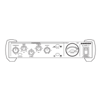
8 MAINS POWER SWITCH - When turned on, acti-
vates the S•com plus.
9 RACK EARS - Used for mounting into a 19-inch
standard rack.
10 TRIGGER- Controls the threshold level that the
Expander/Gate becomes active.
11 GATE SWITCH - Selects either Gate or Expander
mode.
12 RELEASE SWITCH - Selects FAST or SLOW Release
Time for EXPANDER/GATE.
13 THRESHOLD - Used to set the minimum signal
level at which the Compressor circuit begins to
function.
14 ENHANCE - Activates S• com plus’ Enhanced
Spectrum Recovery circuit restoring the high end
loss resulting from extreme Gain Reduction.
15 RATIO - Controls the amount Gain Reduction in
proportion to the amount of signal over the
selected threshold level.
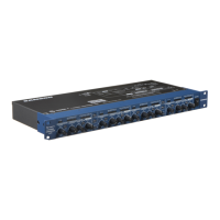
A AC INLET - IEC standard AC Power cable
Connector.
B CHANNEL 2 XLR INPUT - XLR Balanced line
input.
C CHANNEL 2 1/4” TRS INPUT - 1/4” TRS
Balanced line input.
D OPERATING LEVEL SWITCH - Switches the oper-
ating level from -10dB to +4dB.
E CHANNEL 2 KEY INPUT - Input connection
allowing external control of the S•com plus’
Compressor detection circuit.
F CHANNEL 1 KEY OUTPUT - S• com plus’ detec-
tor circuit is sent here. Use the Key Output to
process the compressor’s detector through an
external effect like an equalizer.
 Loading...