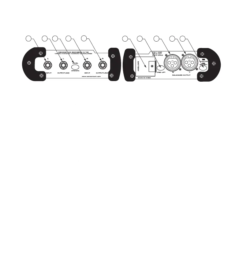
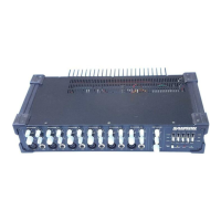
S direct Front and Rear Panel Layout
2 LEFT OUTPUT/LINK - 1/4” output for 2 LEFT OUTPUT/LINK
passing the input signal through to a
stage amplifier or monitor system.
level is switched from instrument GTR to
amplifier speaker SPK level.
5 RIGHT OUTPUT/LINK - 1/4” output for 5 RIGHT OUTPUT/LINK
passing the input signal through to a
stage amplifier or monitor system.
a standard 9 Volt Battery.
engaged, the input ground (
is disconnected from the S direct
direct plus from phantom power to
The S direct plus can operate on a single 9 Volt battery or standard 24-48 volt phan-
tom power. Whenever phantom power is present on the XLR cable that is connected
to the Balanced Output, the S direct plus will automatically switch to phantom power
and disconnect the 9 Volt battery. In fact, when the Battery switch is in, the S direct
plus will sense the voltage and chose which ever is greater. The Phantom/Battery
switch can be used to turn off the battery power when the unit is not in use.