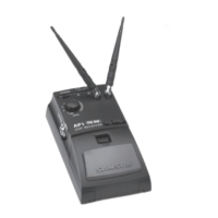
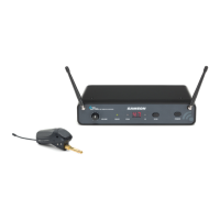
Guided Tour - UR-4 Front Panel
4b: AF (Audio Frequency) Level display - This “ladder” display
(similar to the VU bar meter used on audio devices) indicates the
strength of audio output signal. For optimum signal-to-noise ratio,
adjust the Volume knob (see #3 on the previous page) so that the “0”
segment (third from the top) lights frequently, with only occasional
excursions into the “+3” and “+6” segments. If none of these segments
are lit, little or no signal is being output; see the “Trouble-shooting”
section on page 20 for more details.
4c: “A”/“B” LEDs - These LEDs show you whether signal from the “A”
or “B” receiver is currently being used; when signal is being received,
one of them will be lit. A computer chip inside the UR-4 constantly
scans the two and automatically selects whichever is receiving the
strongest, clearest signal. This “true diversity” switching is completely
inaudible, but it effectively increases overall range while reducing poten-
tial interference and phase cancellation problems.
4d: “Diversity” LED - Lights whenever the UR-4 is powered on.
4e: “Mute” LED - Lights to indicate the absence of carrier signal.
When “MUTE” is lit, either the transmitter Mute switch is in the “on”
position or the transmitter’s channel does not match that of the receiver.
4f: “Power” LED - Lights whenever the UR-4 is powered on.
6