13
English
Installation Procedure
NOTE
1 Voltage range
• Units are suitable for use on electrical systems
where voltage supplied to unit terminal is not
below or above listed range limits.
2 Maximum allowable voltage variation between phases
is 2%.
3 Wire size & type must comply with the applicable local
and national code.
• Wire size: Based on the value of MCA.
• Wire type: 60245 IEC57(IEC) or H05RN-F(CENELEC)
grade or more.
4 MFA is used to select the circuit breaker and the
ground fault circuit interrupter (earth leakage circuit
breaker).
5 MCA represents maximum input current.
• MFA represents capacity which may accept MCA
• Abbreviations
MCA: Min. Circuit Amps. (A)
MFA: Max. Fuse Amps. (A)
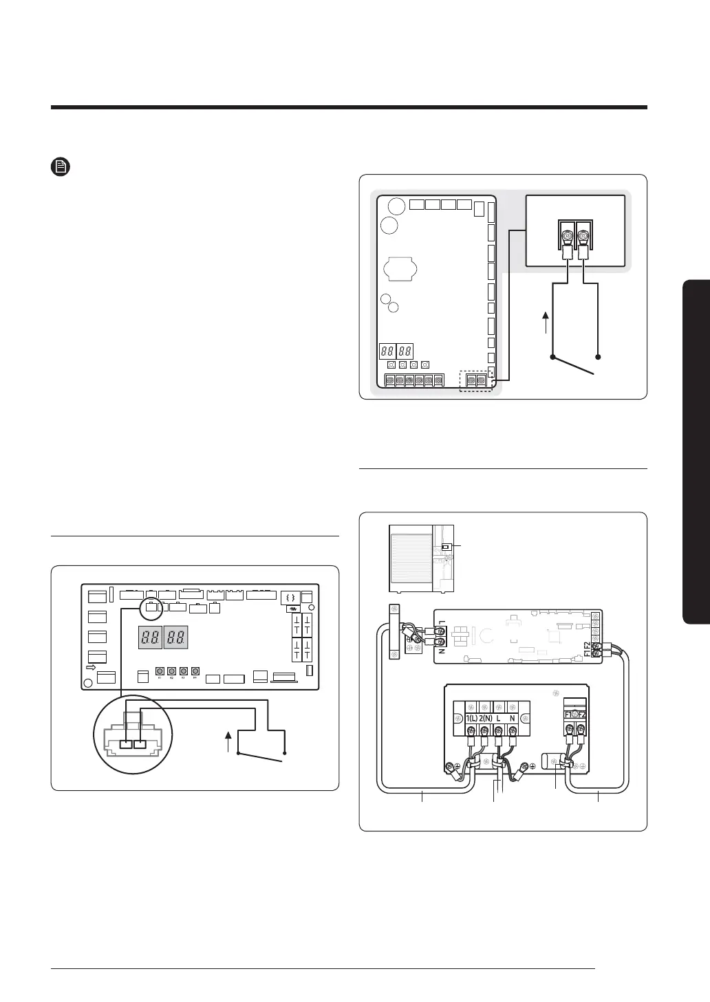
Silence mode controller wiring diagram
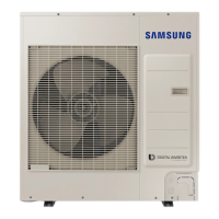
• AC052/071TXADKC
CN001
Outdoor unit
Non-voltage contact
CN001
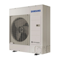
• AC100/120/140/160TXAD*C
Outdoor unit
ASSY Control out
Non-voltage contact
Connecting the outdoor-to-indoor power cable
and the communication cable
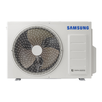
1-phase
For connecting the power and
communication cables
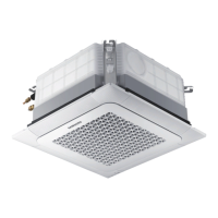
Indoor Unit
Outdoor Unit
Outdoor-to-indoor
power cable
Communication cable
Cable tie
Main power cable
 Loading...