14
Installation Procedure
English
Installation Procedure
3-phase
L
N
F1 F2
1(L)
2(N) L1(R) L2(S)L3(T) N
F1 F2
Indoor Unit
Outdoor Unit
Outdoor-to-indoor
power cable
Communication cable
Cable tie
3-phase 4-wire main
power cable (AC 380V)
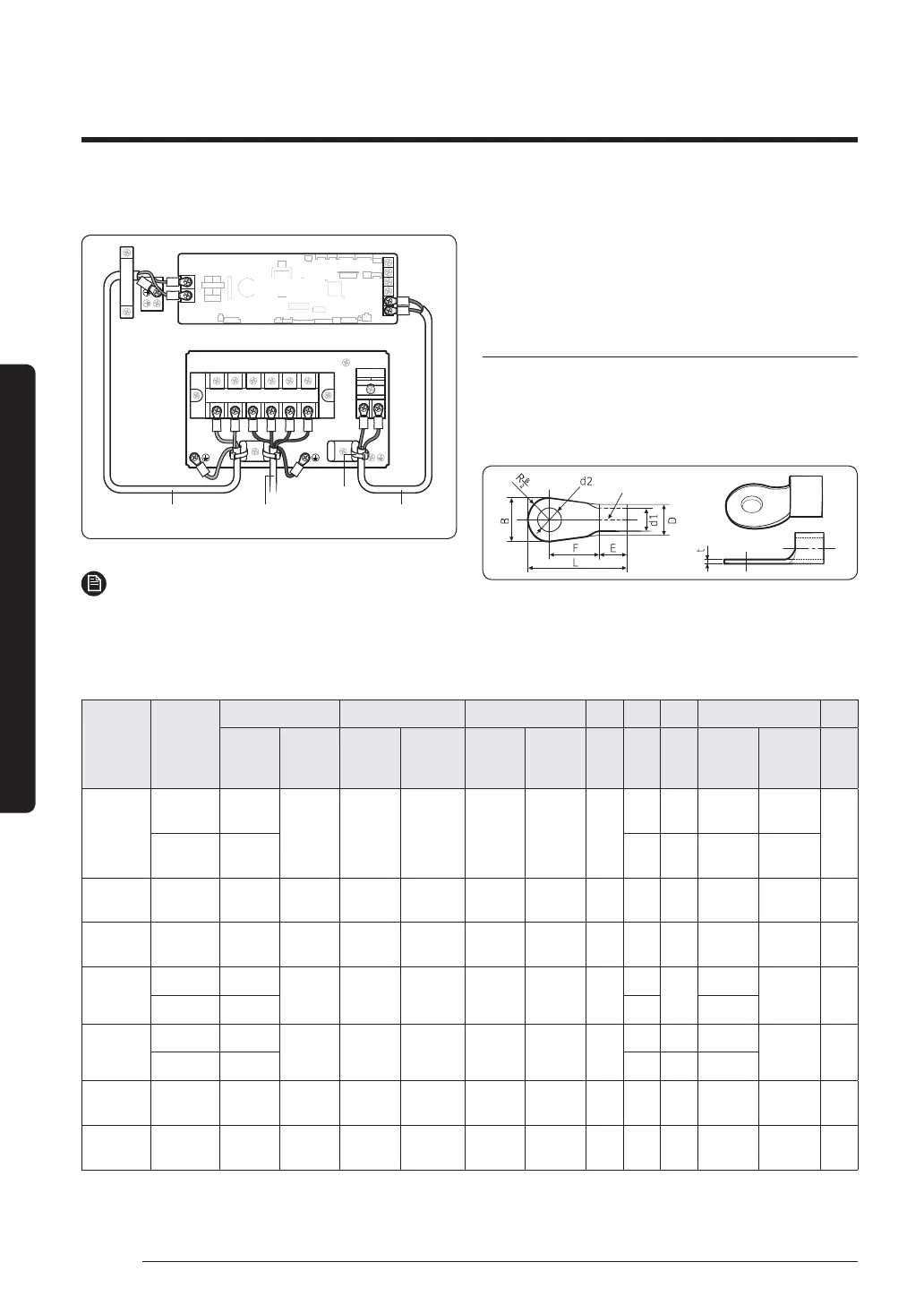
NOTE
• Lay the electrical wiring so that the front cover does
not rise up when doing wiring work and attach the
front cover securely.
• Ground wire for the indoor unit and outdoor unit
connection cable must be clamped to a soft copper
tin-plated eyelet terminal with M4 screw hole(NOT
SUPPLIED WITH UNIT ACCESSORIES).
Outdoor-to-indoor power terminal
specifications
• Connect the cables to the terminal board using the
compressed ring terminal.
• Cover a solderless ring terminal and a connector part
of the power cable and then connect it.
Silver solder
Nominal
dimensions
for cable
(mm²)
Nominal
dimensions
for screw
(mm)
BDd1EFLd2t
Standard
dimension
(mm)
Allowance
(mm)
Standard
dimension
(mm)
Allowance
(mm)
Standard
dimension
(mm)
Allowance
(mm)
Min.
(mm)
Min.
(mm)
Max.
(mm)
Standard
dimension
(mm)
Allowance
(mm)
Min.
(mm)
4/6
49.5
±0.2 5.6
+0.3
-0.2
3.4 ±0.2 6.0
520.0 4.3
+0.2
0
0.9
815.0 928.58.4
+0.4
0
10 8 15.0 ±0.2 7.1
+0.3
-0.2
4.5 ±0.2 7.9 9 30.0 8.4
+0.4
0
1.15
16 8 16.0 ±0.2 9.0
+0.3
-0.2
5.8 ±0.2 9.5 13 33.0 8.4
+0.4
0
1.45
25
812.0
±0.3 11.5
+0.5
-0.2
7.7 ±0.2 11.0
15
34.0
8.4
+0.4
0
1.7
816.5 13 8.4
35
816.0
±0.3 13.3
+0.5
-0.2
9.4 ±0.2 12.5
13 38.0 8.4
+0.4
0
1.8
822.0 1343.08.4
50 8 22.0 ±0.3 13.5
+0.5
-0.2
11.4 ±0.3 17.5 14 50.0 8.4
+ 0.4
0
1.8
70 8 24.0 ±0.4 17.5
+0.5
-0.4
13.3 ±0.4 18.5 20 51.0 8.4
+ 0.4
0
2.0
 Loading...