Do you have a question about the Samsung AM160FNBFGB/EU and is the answer not in the manual?
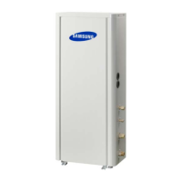
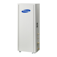
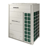
| Model | AM160FNBFGB/EU |
|---|---|
| Type | Heat Pump |
| Cooling Capacity | 16.0 kW |
| Heating Capacity | 18.0 kW |
| Energy Efficiency Class (Cooling) | A++ |
| Energy Efficiency Class (Heating) | A+ |
| Refrigerant | R410A |
| Operating Temperature Range (Heating) | -20°C to 24°C |
| Power Supply | 50Hz |
| Dimensions (Outdoor Unit) | 940 x 330 mm |
Guidelines for servicing electrical parts, harnesses, and product handling during repairs.
Essential safety guidelines for operating and handling electrical components, plugs, and wiring.
Safety and environmental precautions related to refrigerant handling, release, and container management.
Step-by-step procedures for disassembling and reassembling various types of indoor units.
Detailed disassembly instructions for the panel, filter, and internal components of slim 1-way cassette units.
Disassembly procedures for the panel, drain pan, and SPI kit of large slim 1-way cassette units.
Procedures for disassembling the motor, blower, evaporator, and drain pan for BIG DUCT units.
Disassembly steps for the panel, control box, bell-mouth, and drain pan of global 4-way cassette units.
Procedures for disassembling the panel and control box of 360 cassette indoor units.
Disassembly steps for motor, blower, drain pan, evaporator, and control components for slim duct type 1 and 2.
Procedures for disassembling the filter, bracket outlet, and internal components of slim duct type 3 units.
Disassembly steps for filter, control in, drain pan, and evaporator of mid-pressure type 1 duct units.
Procedures for disassembling blower, motor, drain pan, and evaporator of mid-pressure type 2 and high-pressure duct units.
Disassembly steps for electrical parts, fan, motor, and drain pan of ceiling type indoor units.
Procedures for disassembling cabinet parts, electrical parts, blowing, and evaporator parts of console type units.
Disassembly procedures for the cabinet, heat exchanger, and motor/fan of floor standing units.
Steps for disassembling the front grille, control-in, tray drain, heat exchanger, and fan motor of wall-mounted units.
Procedures for detaching the panel-front, cover panel, and control-in for wall-mounted A3050 type units.
Disassembly steps for panel-front, cover-panel, and control-in for wall-mounted Neo Forte EEV units.
Procedures for disassembling the cover control, motor & fan, and control box for GD-S (Big Duct) units.
Guide to troubleshooting various error codes and malfunctions.
General troubleshooting procedures for common symptoms and errors.
Guide to troubleshooting various error codes and malfunctions.
General troubleshooting procedures for common symptoms and errors.
Troubleshooting steps for errors related to the indoor unit's drain pump floating switch.
Troubleshooting steps for errors related to the indoor unit's fan motor operation.
Troubleshooting steps for outdoor temperature sensor errors (open/short).
Diagnosing and resolving errors related to outdoor temperature sensor dislocation.
Troubleshooting steps for Cond Out Temperature Sensor errors (open/short).
Diagnosing and resolving outdoor Cond Out sensor breakaway or defective errors.
Troubleshooting steps for digital compressor discharge temperature sensor errors.
Diagnosing and resolving constant rate compressor discharge temperature sensor errors.
Troubleshooting compressor discharge or top 1/2 temperature sensor errors.
Steps to diagnose and resolve compressor sump temperature sensor dislocation errors.
Troubleshooting steps for suction temperature sensor breakaway or defective errors.
Diagnosing and resolving SUMP temperature sensor errors (open/short).
Troubleshooting steps for high pressure sensor errors (open/short).
Diagnosing and resolving low pressure sensor errors (open/short).
Troubleshooting suction temperature sensor errors (open/short).
Diagnosing and resolving liquid pipe temperature sensor errors (open/short).
Troubleshooting steps for compressor down errors due to high pressure protection control.
Diagnosing compressor down errors due to low pressure protection control.
Steps to diagnose and resolve refrigerant leakage errors.
Steps to diagnose and resolve liquid compression prevention control errors.


 Loading...