SAMSUNG Installation
DCS-816 March 1999
2-5
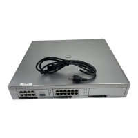
Details of RJ-45 Connections
Eight pins of the RJ-45 connector are assigned to connections of SLT interface ports on the base
board.
Pin No. Circuits/ Functions Remarks
1
8
Tip, 1
st
SLT port (STN 13) on the base board
Ring, 1
st
SLT port (STN 13) on the base board
OPX Circuit
No polarity
2
7
Tip, 2
nd
SLT port (STN 14) on the base board
Ring, 2
nd
SLT port (STN 14) on the base board
OPX Circuit
No polarity
3
6
Tip, 3
rd
SLT port (STN 15) on the base board
Ring, 3
rd
SLT port (STN 15) on the base board
No polarity
4
5
Tip, 4
th
SLT port (STN 16) on the base board
Ring, 4
th
SLT port (STN 16) on the base board
No polarity
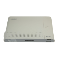
MDF CABLING
BOTTOM
VIEW
FRONT VIEW
AFTER REMOVING
THE FRONT COVER
FROM
50-PIN CHAMP
FROM
8-PIN RJ-45
Technical Manuals Online! - http://www.tech-man.com
 Loading...