SAMSUNG Installation
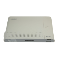
DCS-816 March 1999
i
Table of Contents
PART 1. SITE REQUIREMENTS..................................................................................... 1-1
PART 2. INSTALLING THE BASIC KSU …………………………………………………… 2-1
2.1 System Configuration and Capacity.....................................................................................................2-1
2.2 Unpacking and Inspection....................................................................................................................2-2
2.3 Mounting the KSU (Figure 2-1) ............................................................................................................2-2
2.4 Grounding the KSU (Figure 2-2) ..........................................................................................................2-3
2.5 MDF Cabling (Figure 2-3).....................................................................................................................2-3
2.6 External Battery Connection (Figure 2-4).............................................................................................2-6
2.7 Selecting Options on the Basic KSU (Figure 2-5) ................................................................................2-7
PART 3. INSTALLING OPTION CARDS AND TRUNK CARDS (FIGURE 3-1).............. 3-1
3.1 SIO1 Option Card (Figure 3-2).............................................................................................................3-2
3.2 AA Option Card (Figure 3-2) ................................................................................................................3-2
3.3 8TRK Card (Figure 3-3)........................................................................................................................3-3
3.4 2/4BRI Card (Figure 3-3)......................................................................................................................3-3
3.5 4TRK Card (Figure 3-4)........................................................................................................................3-4
PART 4. POWER-UP PROCEDURE ………………………………………………………..4-1
4.1 Connect Power to the System (Figure 4-1, 4-2)...................................................................................4-1
4.2 Monitor LED Indication and Memory Backup Selection .......................................................................4-3
4.3 PCB Verification ...................................................................................................................................4-3
4.4 Default Trunk and Station Numbering..................................................................................................4-3
PART 5. CONNECTING PSTN CIRCUITS .………………………………………………….5-1
5.1 Safety Precautions ...............................................................................................................................5-1
5.2 Loop-Start Lines (Figure 5-1) ...............................................................................................................5-2
5.3 Off Premise Extension (OPX) (Figure 5-2) ..........................................................................................5-3
5.4 ISDN BRI Lines (Figure 5-3) ................................................................................................................5-4
PART 6. CONNECTING STATION EQUIPMENT ………………………………………...6-1
6.1 Safety Precautions ...............................................................................................................................6-1
6.2 Digital Keysets (Figure 6-1)..................................................................................................................6-2
6.3 Single Line Telephones (Figure 6-2)....................................................................................................6-3
6.4 Door Phone and Door Lock Release (Figure 6-3)................................................................................6-4
6.5 CTM - CTI Module (TAPI) (Figure 6-4) ................................................................................................6-5
6.6 ISDN TE (ISDN Phone, G4 FAX, etc) (Figure 6-5) ..............................................................................6-6
PART 7. CONNECTING OPTIONAL EQUIPMENT ……………………………………….7-1
7.1 Music-on-Hold/ Background Music (Figure 7-1)...................................................................................7-1
7.2 External Paging (Figure 7-2) ................................................................................................................7-2
7.3 Common Bell (Figure 7-3)....................................................................................................................7-3
7.4 Ring Over Page....................................................................................................................................7-4
7.5 Station Message Detail Recording (SMDR) (Figure 7-4).....................................................................7-4
7.6 PC Programming (Figure 7-5)..............................................................................................................7-5
7.7 Remote Programming (Figure 7-6)......................................................................................................7-6
7.8 Power Failure Transfer.........................................................................................................................7-6
7.9 Voice Mail/ Auto Attendant (Figure 7-7) ...............................................................................................7-7
7.10 Information on DCS-816 Serial Interface (Figure 7-8) .......................................................................7-8
Technical Manuals Online! - http://www.tech-man.com
 Loading...