6-1
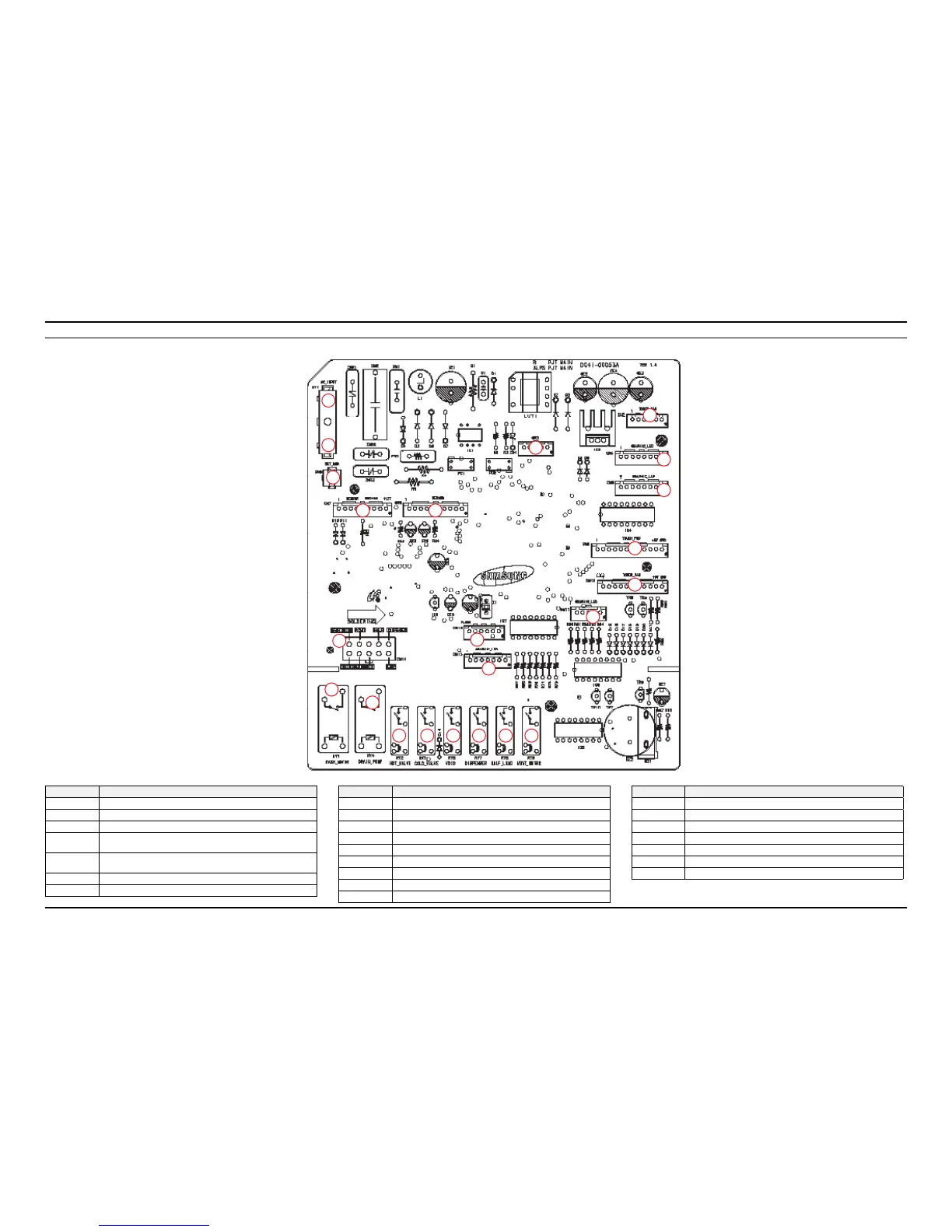
6. PCB Diagram
6. PCB Diagram
6-1. Old PBA - Main PCB
Location Description
1 PBA Power (120V, AC1)
2 PBA Power (120V, AC2)
3 NC
4
12V, 5V, DC GND, Power Relay Driver, Heater Relay Driver, Half
Load Sensor, Turbidity Sensor, Rinse Aid Sensor
5
Low Water Level Sensor, Overow Sensor, Cold Water Counter,
Leakage Sensor, Temperature sensor, Door Sensor
6 Electric Driving connector
7 Circulation Motor Driving Relay
1
2
3
4 5
6
7
8
9 10 11 12 13 14
15
16
17
18
19
20
21
22
23
Location Description
8 Drain Pump Driving Relay
9 NC
10 Inlet Valve Driving Relay
11 NC
12 Dispensor Driving Relay
13 Distributor Motor Driving Relay (only DMR77)
14 Fan Motor Driving Relay
15 Display LED Driving Connector
16 Micom Writer Connector
Location Description
17 Display LED Driving Connector (only DMR77)
18 Touch-Key, LED Driving, 5V, DC GND
19 Touch-Key, LED Driving, 5V, DC GND (only DMR77)
20 Display LED Driving Connector
21 Display LED Driving Connector (only DMR77)
22 NC
23 LED, 12V Driving
 Loading...