Do you have a question about the Samsung NV51K6650D and is the answer not in the manual?
Introduces the purpose and scope of the service manual.
Outlines general safety guidelines for appliance repair and usage.
Provides critical safety instructions to prevent fire, shock, and injury.
Shows the location of model and serial number labels and tech sheets.
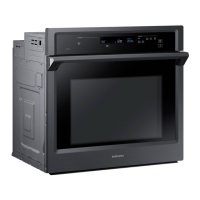
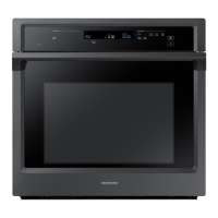
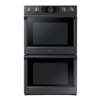
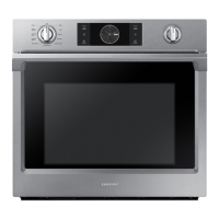
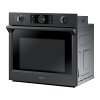
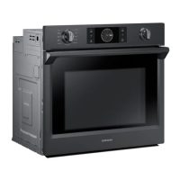
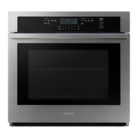
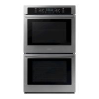
Details technical specifications for basic and new models.
Lists and describes the included accessories with their part numbers.
Lists necessary tools for disassembly and reassembly procedures.
Step-by-step guide to removing the main back cover wire.
Procedure for removing the main Printed Circuit Board (PCB).
Steps to remove the Switched-Mode Power Supply (SMPS) PCB.
Instructions for disassembling the control box unit.
Steps to remove the auxiliary Sub Printed Circuit Board (PCB).
Guide for removing the knob lighting module assembly.
Procedure for removing the door latch and switch plunger.
Steps to remove the broil heating element.
Instructions for removing the bake heating element.
Steps to remove convection element, fan, and motor.
Procedure for removing the oven lamp assembly.
Steps to remove the partition switch assembly.
Guide for removing the temperature sensor (thermistor).
Instructions for removing the oven door.
Instructions for replacing the oven door.
Steps to remove door handle and inner glass.
Procedure for removing and replacing the door gasket.
Steps to remove the Wi-Fi communication module.
Instructions for removing the steam set components.
Overview of the steam assembly structure and components.
Steps to remove the sub steam generator assembly.
Procedure for removing the AC pump motor.
Lists error codes and their corresponding causes and solutions.
Guides on diagnosing and resolving electrical issues.
Shows the layout and component identification for the upper oven PCB.
Shows the layout and component identification for the lower oven PCB.
Illustrates the Printed Circuit Board Assembly (PBA) for the LCD display.
Details the layout and connections of the Sub Printed Circuit Board Assembly (PBA).
Provides the electrical schematic for the upper oven.
Provides the electrical schematic for the lower oven.