OfficeServ 7100 System Description
© SAMSUNG Electronics Co., Ltd.
2-3
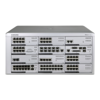
2.2 Cabinet Configuration
OfficeServ 7100 is configured of the main device with a basic cabinet and OfficeServ
solution. The Main device cabinet is a one stage shelf composed of three slots and consists
of a control part on the main slot and two subscriber parts on the universal slot.
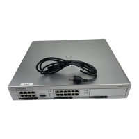
Figure 2.1 Configuration of OfficeServ 7100 Cabinet
Table 2.1 Configuration in the Back side of OfficeServ 7100
Power on/off OfficeServ 7100 system.
Connector to connect the power cable
The LED turns on while applying AC power.
The LED turns on while the DC power normally comes out.
Socket to connect an external battery
Lug to ground the system communication
 Loading...