91
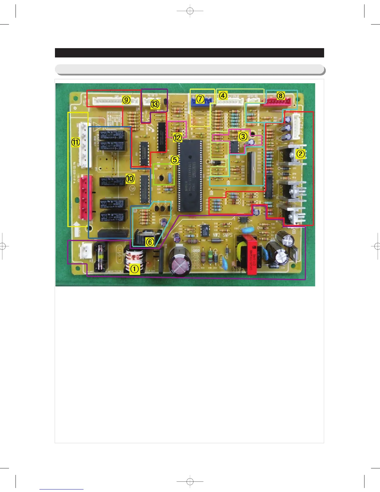
6-1) PCB L ayout with part position (Main Board)
6. PCB DIAGRAM
1. DC12V,5V, & GND are supplied from SMPS PCB.
2. FAN MOTOR driving part : Supply the power from 8.3V~12V to motor according to the motor type(F,R,C,ICE).
3. EEPROM : Save and record every kinds of data.
4. Transmit inputted signals from every sensor into MICOM after eliminate the noise.
5. Departure part : Generate the CLOCK which needs to conrol MICOM program RESET control circuit part :
Initialize the program by sensing power ON/OFF.
6. BUZZER Circuit
7. PLC Input / Output
- PLC (Power Line communication)
* Option(PLC module is not inserted unless specified occasion.)
8. Operate ICE-MAKER, supply power to MOTOR, and sense the variation of switch.
9. Display driving part : Display LED & detect KEY state.
10. Relay part which controls AC load : Operate by receiving the driving signals of MICOM through Sink IC.
(RY75/RY76's Relay to LED Lamp operation use.(DC12V)
11. Connector part : Connect AC load.
12. DIODE option setting part : Set the option
13. Inverter Control part
NW-미주향-AC 2010.6.8 3:48 PM 페 이 지 9 1 i n
 Loading...