73
10) If Humidity Sensor has trouble
ERROR Code
Bad contact of connector /insert correctly
Is MAIN PCB
Connector CN30 inserted
correctly?
Is Humidity Sensor
unit normal?
Is the voltage between
MAIN PCB Connector CN30-”3”(Brown) and
J23 JUMMPER normal?
Is input voltage of
ICO1 MICOM #81 normal?
Start
NO
YES
YES
YES
YES
DATA2. Humidity Sensor Table
Replace the Humidity Sensor
NO
Recheck the PCB & Wire Terminal connection
NO (1.0V > Measurement < 3.5V)
Check the iced-solder, solder
bringing, disturbed solder
Exchange the PCB
NO
No trouble with PCB temperature sensor.
Recheck the bad contact ofthe connection
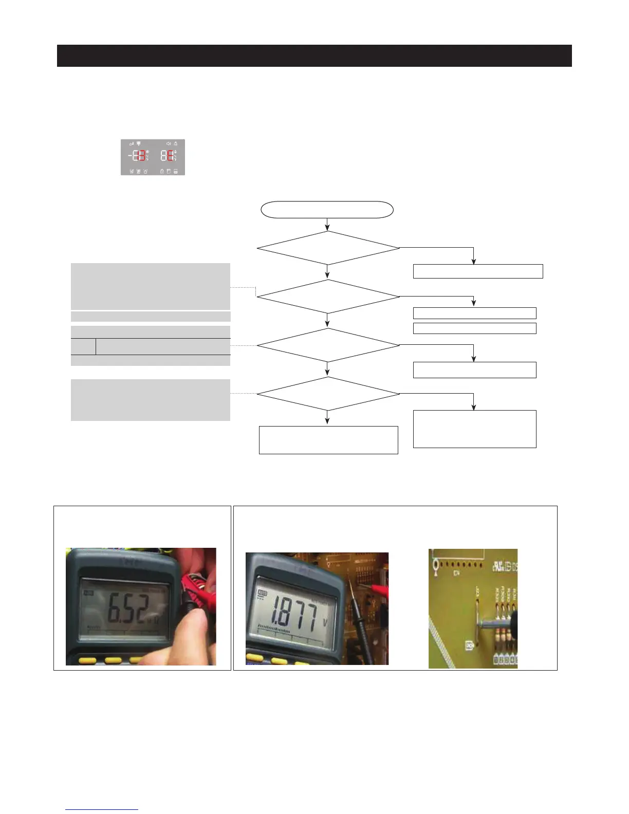
** Measuring point of resistance value according to
Sensor"
Humidity : CN30 ”1” ↔ ”3”
Resistance value with opened : about 50Ω
** 0Ω: Short trouble /Ω∞: Open trouble
Sensor MICOM/Connector number
Voltage measured between 3.5V ~ 1.0V
Measuring voltage of ICO1 MICOM #81,
CN30-"3"(Brown) and J23 JUMMPER from
PCB typical Ground part are similar.
→ Check the voltage of Resistance, R321
☞
Checking method ofHumidity Sensor resistance
CN30-"3"(Brown) ↔ "1"(Gray)
- Compare the temperature table after the measure.
Refer to circuit diagram in the manual
Humidity
Connector CN30-"3"(brown) to
J23 JUMMPER PCB typical Ground
Start
YES
YES
YES
☞
Checking method ofHumidity Sensor voltage.
- Measure the voltage of Resistance, R321(IC01 MICOM #81)
on PCB or CN30-"3"(Brown)
↔
J23 JUMMPER
- Compare the temperature table after the measure.
Measuring voltage of CN30-"3"(Brown)
↔
J23 JUMMPER
are below
PCB Typical Ground
J23 JUMMPER