Do you have a question about the Samsung SCA30 and is the answer not in the manual?
Procedure for checking leakage current with the unit powered on.
Ensuring continued X-ray protection by using the correct picture tube.
Techniques to reduce component damage from static electricity.
Warning against altering mechanical or electrical design to avoid safety hazards.
Safety precautions for servicing chassis connected to AC power cord.
Importance of using exact replacement parts for safety characteristics.
Step-by-step guide for replacing the video light unit bulb.
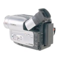
Detailed specifications for NTSC models SCA30, SCA33, SCA35, SCA80, SCA85.
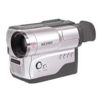
Detailed specifications for PAL models VP-A30, VP-A31, VP-A33, VP-A34, VP-A800, VP-A850.
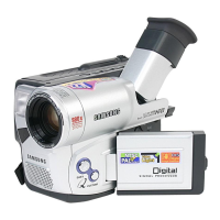
Comparison of features across different NTSC and PAL models.
Step-by-step instructions for removing various camera cabinet parts.
Diagram showing the location of different circuit boards within the unit.
Diagrams illustrating the connections between various PCBs and components.
Procedure for aligning and checking the mechanical operation of the unit.
Steps for adjusting various camera functions and parameters.
Procedures for adjusting the Electronic Viewfinder (EVF) settings.
Procedures for adjusting the Color Viewfinder (CVF) settings.
Procedures for adjusting the Video Cassette Recorder (VCR) section.
Exploded view and parts list for the first cabinet assembly.
Exploded view and parts list for the second cabinet assembly.
Exploded view and parts list for the third cabinet assembly.
Exploded view and parts list for the fourth cabinet assembly.
Exploded view and parts list for the Electronic Viewfinder (EVF).
Exploded view and parts list for the Color Viewfinder (CVF).
Exploded view and parts list for mechanical components (part 1).
Exploded view and parts list for mechanical components (part 2).
Exploded view and parts list for mechanical components (part 3).
Component and conductor side diagrams for the Main PCB.
Component and conductor side diagrams for the Rear PCB.
Component and conductor side diagrams for the Front PCB (with and without EIS).
Component and conductor side diagrams for the Color Viewfinder (CVF) PCB.
Component and conductor side diagrams for the Electronic Viewfinder (EVF) PCB.
Diagram of the CCD PCB.
Diagram of the Function PCB.
Schematic diagram for the DC/DC converter on the Main PCB.
Schematic diagram for the system control and servo circuits on the Main PCB.
Schematic diagram for the normal video circuits on the Main PCB.
Schematic diagram for the Hi-8 video circuits on the Main PCB.
Schematic diagram for the mono audio circuits on the Main PCB.
Schematic diagram for the stereo audio circuits on the Main PCB.
Schematic diagram for the camera section on the Main PCB.
Schematic diagram for the Rear PCB.
Schematic diagram for the CCD component.
Schematic diagram for the Color Viewfinder (CVF).
Schematic diagram for the Electronic Viewfinder (EVF).
Schematic diagram for the Front PCB with Electronic Image Stabilization.
Schematic diagram for the Front PCB without EIS (Mono audio).
Schematic diagram for the Front PCB without EIS (Stereo audio).
Schematic diagram for the Function PCB.
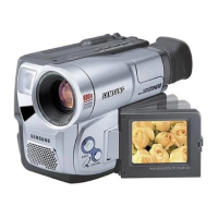
| LCD Screen Size | 2.7 inches |
|---|---|
| Sensor Type | CCD |
| Focus System | Auto / Manual |
| Effective Pixels | 800k |
| Recording Media | MiniDV tape |
| Battery Type | Lithium-ion |