Samsung Electronics5-38
Alignment and Adjustment
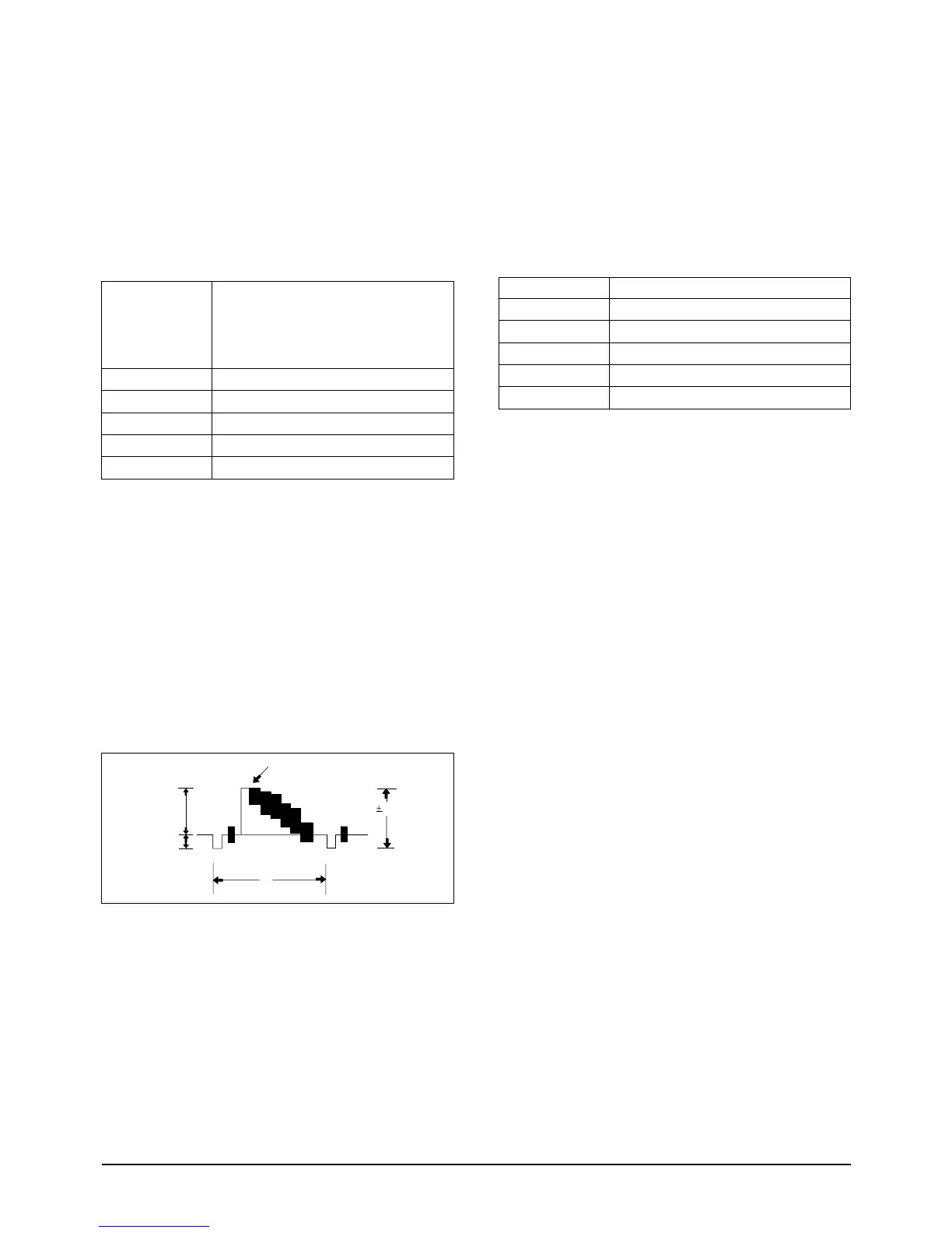
2-9. PB Output Level (Hi8)
: This adjustment is performed to set the sync-
tip level of the composite video signal.
Maladjusted Y-FM carrier impact to the play-
back picture, there may be black or white dot
noise.
a. Preparations
b. Connect a power source.
c. Get into the VCR adjustment mode.
d. Press the “DATE/TIME(MODE UP)/TITLE
(MODE DOWN)” button of CAMCORDER so
as to select the address 14.
e. Insert a Hi-8 standard color bar tape and press
the PLAY button.
f. Connect the oscilloscope counter to the
addressed Test Point.
g. Press the “C/RESET(DATA UP)/Z/RTN(DATA
DOWN)” button so that the CN605 PIN13 is
1.0±0.02Vp-p from SYNC to peak level.
h. Be sure to press the “MENU/ENTER(CON-
FIRM)” button of CAMCORDER to memorize
setting.
i. Reset the power source so as to fix the new data
to the camcorder’s EEPROM.
2-10. Y-FM Carrier (Hi8)
: This adjustment is performed to set the sync-
tip level of the composite video signal.
Maladjusted Y-FM carrier impact to the play-
back picture, there may be black or white dot
noise.
a. Preparations
b. Connect a power source.
c. Get into the VCR adjustment mode.
d. Press the “DATE/TIME(MODE UP)/TITLE
(MODE DOWN)” button of CAMCORDER so
as to select the address 15.
e. Insert a Hi-8 Tape to the camcorder.
f. Press the START/STOP button on the Rear
board so as to set the camcorder to RECORD-
ING mode.
g. Connect the frequency counter to the addressed
Test Point.
h. Press the “C/RESET(DATA UP)/Z/RTN(DATA
DOWN)” button so as to set the frequency to
5.99MHz ±0.02MHz
i. Be sure to press the “MENU/ENTER(CON-
FIRM)” button of CAMCORDER to memorize
setting.
j. Reset the power source so as to fix the new data
to the camcorder’s EEPROM.
FREQUENCY COUNTER
NONE
IC 201 PIN 13
15
Y-FM CARRIER (HI-8)
EQUIPMENT
OTHER
TEST POINT
ADDRESS
NAME
HI8 TAPE FOR RECORDINGTAPE