CONTENTS
1.
GENERAL
DESCRIPTION
1-1.
Safety
Precautions
...........scssssessssesssesssesseseseseee
1-1
1-2.
Electrostatically
Sensitive
(ES)
Devices
.........
4-2
1-3.
General
Information
rs
1-4.
Replacement
Procedure
for
Leadless
(Chip)
COMPOMENL
.......ecsessseecsesssesesesssecsseessecssessseseneesues
1-4
1-5.
How
to
Read
Leadiess
(Chip)
Component
Va
RG
ss
isesscsesscadscecessshesacestessenscsvehertsteareqscosvevtees
1-6
1-6.
Cleaning
and
Lubrication
..
1-8
1-7.
Abbreviations
1-9
2.
DISASSEMBLY
2-1,
Instrument
Disassembly
....
2-1
2-2.
Circuit
Board
Disassembly
...
9.9
2-3.
Tape
Transport
Mechanism
Identification
........
2-4
2-4.
Housing
Ass'y
Removal
&
Reassembly
....
2-5.
Cylinder
Ass'y
Removal
&
Reassembly
2-6.
Reel
Disk
Ass'y
Removal
oa
2-7.
Loading
&
Capstan
Motor
Ass'y
Removal
&
Reassembly
“17
2-8.
Tape
Transport
Ass'y
Removal
mee
3.
MECHANICAL
ADJUSTMENT
3-1.
Tape
Transport
System
..
3-1
3-2.
Reel
Torque
3-6
4,
ELECTRICAL
ADJUSTMENT
4-1.
Preparation
4-1
4-2,
Program
Switch
Timing
Chart
.
4-2
4-3.
Servo,
Audio,
Tuner
&
OSD
Section
.
4.3
4-4.
Video
Section
4-4
5.
ELECTRICAL
PARTS
LIST
5-1.
General
Information
.......ssssecsssesccseesseesssesesnees
5-1
5-2.
Electrical
Replacement
Parts
List
.......cssse-
5-2
6.
MECHANICAL
EXPLODED
VIEW/
PARTS
LIST
6-1,
Instrument
Assembly
.
6-2
6-2.
Mechanical
Parts
(1)
;
Top
View
.
64
6-3.
Mechanical
Parts
(2)
;
Bottom
View
..
-
6-6
6-4.
Housing
ASSeMDLy
.......sccsecsseesseeetsneee
GB
7.
BLOCK
DIAGRAMS
7-1.
Total
Wiring
Diagram
7-2.
Cylinder
Phase
Control
....
Be
7-3.
Cylinder
Speed
Control
93
7-4.
Capstan
Phase
Control
..
7-4
7-5.
Capstan
Speed
Control
.
7-4
7-6.
Audio
Playback
Process
7-5
7-7.
Audio
Record
Process
..
ae
7-8.
Luminance
Playback
Process
(VXK-306/307)..
7.6
7-9,
Luminance
Playback
Process
(VXK-336/337)..
7.7
7-10.
Luminance
Record
Process
(VXK-306/307)...
7.8
7-11,
Luminance
Record
Process
(VXK-336/337)...
7.9
7-12.
Chrominance
Playback
Process
(VXK-306/307)
7-13.
Chrominance
Playback
Process
(VXK-336/337)
7-14.
Chrominance
Record
Process
(VXK-306/307)
...ecseeseessssesesssecsesssssnessarenneeevess
7-15.
Chrominance
Record
Process
ne
(VXK=336/337)
scssssstseseslececscoscssscedocesctssstenseuss
7-13
8.
CIRCUIT
BOARDS
a1
RES
WIAOF
a.
acvcccevsvasssvcssossenesistestendnastvenedeancscletees
BO,
UES:
Ss
stats
Scat
-
8-3.
Pre-Amp
(VXK-306/307)
8-4,
Pre-Amp
(VXK-336/337)
...
8-5.
Main
8-6.
Function/Timer
(VXK-306/336)
8-7,
Function/Timer
(VXK-307/337)
...
9.
SCHEMATIC
DIAGRAMS
9-1.
Regulator
9-2.
Power
9-3.
System
Control
...
9-4.
SOLO
wossesessseees
9-5.
Luminance/Chrominance
9-6.
Pre-Amp
(VXK-306/307)
9-7.
Pre-Amp
(VXK-336/337)
9-8.
Audio
9-9.
Tuner
...
9-10.
V.P.S
(OPTION)
.
9-11.0.8.D
9-12.
Function/Timer
9-13.
Remote
Control
..
1.
GENERAL
DESCRIPTION
lhe
atlas
1-1.
SAFETY
PRECAUTIONS
1.
Before
returning
a
Video
Cassette
Recorder
to
the
customer,
always
make
a
safety
check
of
the
entire
instrument,
including,
but
not
limited
to
the
following
items:
a.
Be
sure
that
no
built-in
protective
devices
are
defective
and/or
have
been
defeated
during
servicing.
(1)
Protective
shields
are
provided
on
this
chassis
to
protect
both
the
technician
and
the
customer.
Correctly
replace
all
missing
protective
shields,
including
any
removed
for
servicing
convenience.
(2)
When
reassembling
the
instrument,
be
sure
to
put
back
in
place
all
protective
devices,
including,
but
not
limited
to
nonmetallic
control
knobs,
insulating,
fish
papers
adjustment
and
compartment
covers/shiclds,
and
isolauon
resistor/capacitor
networks.
Do
not
operate
this
instrument
or
permit
it
to
be
operated
without
all
protective
devices
correctly
installed
and
functioning.
b.
Be
sure
that
there
are
no
cabinet
openings
through
which
an
adult
or
child
might
be
able
to
insert
their
fingers
and
contract
a
hazardous
voltage.
Such
openings
include,
but
are
not
limited
to,
(1)
excessively
wide
cabinet
ventilation
slots,
and
(2)
improperly
fitted
and/or
incorrectly
secured
cabinet
covers.
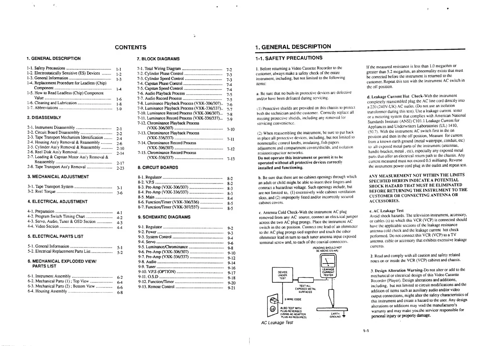
c.
Antenna
Cold
Check-With
the
instrument
AC
plug
removed
from
any
AC
source,
connect
an
electical
jumper
across
the
two
AC
plug
prongs.
Place
the
instrument
AC
switch
in
the
on
position.
Connect
one
lead
of
an
ohmmeter
to
the
AC
plug
prongs
tied
together
and
touch
the
other
ohmmeter
lead
in
turn
to
each
tuner
antenna
input
exposed
terminal
screw
and,
to
cach
of
the
coaxial
connectors.
(READING
SHOULD
NOT
BE
ABOVE
0.5
mA)
LEAKAGE
CURRENT
TESTER
TEST
ALL
EXPOSED
METAL
SURFACES
2-WIRE
CODE
ALSO
TEST
WITH
PLUG
REVERSED
(USING
AC
ADAPTER
PLUG
AS
REQUIRED)
AC
Leakage
Test
EARTH
GROUND
™
If
the
measured
resistance
is
less
than
1.0
megaohm
or
greater
than
5.2
megaohm,
an
abnormality
exists
that
must
be
corrected
before
the
instrument
is
returned
to
the
customer.
Repeat
this
test
with
the
instrument
AC
switch
in
the
off
position.
d.
Leakage
Current
Hot
Check-With
the
instrument
completely
reassembled
plug
the
AC
line
cord
directly
into
a
220
(240V-UK)
AC
outlet.
(Do
not
use
an
isolation
transformer
during
this
test).
Use
a
leakage
current
tester
or
a
metcring
system
that
complies
with
American
National
Standards
Institute
(ANSI)
C101.1
Leakage
Current
for
Appliances
and
Underwriters
Laboratories
(UL)
1410,
(50.7).
With
the
instrument
AC
switch
first
in
the
on
position
and
then
in
the
off
position,
Measure
for
current
{rom
a
known
earth
ground
(metal
waterpipe,
conduit,
etc)
to
all
caposed
metal
parts
of
the
instrument
(antennas,
handle
bracket,
metal
,
etc),
especially
any
exposed
metal
parts
that
offer
an
electrical
retum
path
to
the
chassis.
Any
current
measured
must
not
exceed
0.5
milliamp.
Reverse
the
instrument
power
cord
plug
in
the
outlet
and
repeat
test.
ANY
MEASUREMENT
NOT
WITHIN
THE
LIMITS
SPECIFIED
HEREIN
INDICATE
A
POTENTIAL
SHOCK
HAZARD
THAT
MUST
BE
ELIMINATED
BEFORE
RETURNING
THE
INSTRUMENT
TO
THE
CUSTOMER
OR
CONNECTING
ANTENNA
OR
ACCESSORIES.
e.
AC
Leakage
Test
Avoid
shock
hazards.
The
television
instrument,
accessory,
or
cables
(s)
10
which
this
VCR
(VCP)
is
connected
should
have
the
applicabic
sections
of
the
leakage
resistance
antenna
cold
check
and
the
leakage
current
hot
check
performed.
Do
not
connect
this
VCR
(VCP)
toa
TV
antenna,
cable
or
accessory
that
exhibits
excessive
leakage
currents.
2.
Read
and
comply
with
all
caution
and
safety
related
notes
on
or
inside
the
VCR
(VCP)
cabinet
and
chassis.
3.
Design
Alteration
Warning-Do
not
alter
or
add
to
the
mechanical
or
electrical
design
of
this
Video
Cassette
Recorder
(Player).
Design
alterations
and
additions,
including,
but
not
limited
to
circuit
modifications
and
the
addition
of
items
such
as
auxiliary
audio
and/or
video
output
connections,
might
alter
the
safety
characteristics
of
this
instrument
and
create
a
hazard
to
the
user.
Any
design
alicrations
or
additions
may
void
the
manufacturer's
warranty
and
may
make
you,the
servicer
responsible
for
personal
injury
or
property
damage.
 Loading...