CWFL-3000/4000/6000 Series
E19
Ultra-low water level
alarm
E19 shown with
alarm sound
The unit runs normally under set
values; the water pump, compressor,
condenser fans and heater of the
high/low temp. system shut down
Automatic clearing
E20
Exhaust temp. sensor
failure alarm
E20 shown with
alarm sound
Each refrigeration part runs under
usual procedures
Automatic clearing
E21
Ultra-high exhaust
temp. alarm
E21 shown with
alarm sound
Each refrigeration part runs under
usual procedures
Automatic clearing
<5> Alarm and communication output
For ensuring the equipment will not be damaged when abnormal condition occurs
in the chiller, it has alarm protection function.
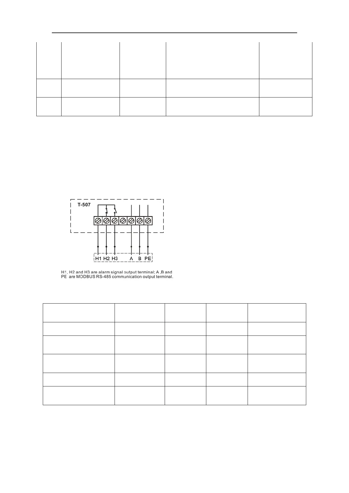
1. Alarm and MODBUS RS-485 communication output wiring diagram.
2. Working condition table of alarm signal
Unit condition
Built-in buzzer of
temp. controller
OUT
H1
H2
OUT
H1
H3
ILUS
Working normally No Sound Disconnection Breakover
E00、E01、E08、E09、
E10、E12、E13、E15
Sounds Breakover Disconnection
E02、E03、E11、E14、E16
E17、E18、E20、E21
Sounds Disconnection Breakover
E04、E05、E06、E07 Sounds Breakover Disconnection Optional
E19 Sounds Breakover Disconnection
Activate after output
terminal delaying
Note: The flow alarm is connected to the normally open relay and normally closed relay
contacts, requiring operating current less than 5A, working voltage less than 300V.
11