EasyManua.ls Logo

S&A CW-5000 Series - User Manual

S&A CW-5000 Series
13 pages
Print Icon
To Next Page IconTo Next Page
Loading...

CW-5000/5200 Series Industrial Chiller
Malfunction Testing and Repair Handbook
Question and Answer IconNeed help?

Do you have a question about the S&A CW-5000 Series and is the answer not in the manual?

Summary

Chiller Alarm (Red Light Flash) - With Water Circulation

Flow Switch and Relay Testing

Diagnose flow switch and relay issues causing continuous water circulation alarms.

Chiller Alarm - Water Current Intermittent

Troubleshooting Intermittent Water Current Alarms

Diagnose and resolve issues related to pipe choking, power supplies, or DC pump failures.

Chiller Alarm - Without Water Circulation

Diagnosing No Water Circulation Alarms

Troubleshoot low water level, power supply, or DC pump issues causing no water circulation.

CW-5000 Series Temperature Controller Alarms

Troubleshooting E1: Ultrahigh Room Temperature

Addresses E1 alarms for high room temperature, focusing on ventilation and cleaning solutions.

Troubleshooting E2: Ultrahigh Water Temperature

Diagnose E2 alarms by checking fan, thermostat, compressor, and refrigerant system components.

Troubleshooting E3: Ultralow Room Temperature

Addresses E3 alarms for low room temperature, often related to ambient conditions and water addition.

Troubleshooting E4;E5 Sensor Failures

Diagnose E4 (room temp) and E5 (water temp) sensor failures, including wire and controller issues.

Machine Does Not Work When Power Is On

Troubleshooting Power-On Issues

Diagnose why the machine does not work on power-up, checking fuses and power supplies.

Overview

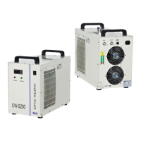
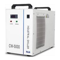
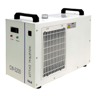
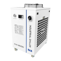
This document outlines the malfunction testing and repair procedures for the S&A CW-5000/5200 Series Industrial Chiller. This chiller is designed to provide cooling for industrial applications, ensuring stable operation of connected equipment by maintaining a consistent water temperature.

Function Description

The S&A CW-5000/5200 Series Industrial Chiller serves as a crucial component in various industrial setups, primarily to dissipate heat generated by machinery. Its core function is to circulate cooled water through a system, absorbing heat from the application and then releasing that heat into the ambient environment. This process is managed by a temperature controller, specifically the T-503 model for the CW-5000 series, which monitors and regulates the water temperature to prevent overheating of the connected equipment. The chiller is equipped with a refrigeration system, including a compressor, condenser, and evaporator, to achieve the necessary cooling. A pump circulates the water, and a flow switch ensures that water is indeed moving through the system, triggering an alarm if circulation is interrupted.

Usage Features

The chiller is designed for straightforward operation and includes several features to ensure reliable performance and user awareness. When the chiller is powered on, it initiates water circulation. The temperature controller displays the current water temperature and allows for setting the desired temperature. In normal operation, a green light indicates proper functioning.

A key usage feature is its alarm system, which provides immediate feedback on potential issues. Alarms are indicated by a red light flash and, in the case of the T-503 controller, an audible buzzer accompanied by a specific error code display. These codes, such as E1 for ultrahigh room temperature, E2 for ultrahigh water temperature, E3 for ultralow room temperature, E4 for room temperature sensor failure, and E5 for water temperature sensor failure, guide the user in diagnosing problems. The alarm sound can be temporarily suspended by pressing any button on the controller, but the visual display of the alarm condition persists until the underlying issue is resolved.

For optimal performance, the chiller requires a ventilated location, with specific clearances for air inlet (at least 30cm from obstructions) and air outlet (at least 50cm). Regular cleaning of the dust gauze is also essential to maintain efficient heat exchange and prevent the accumulation of dust on the condenser. The chiller operates with purified water, and users are advised to ensure the water level in the tank is above the pump inlet.

Maintenance Features

The manual provides comprehensive guidance for troubleshooting and repairing common malfunctions, emphasizing a systematic approach to maintenance.

Alarm with Water Circulation (Red Light Flash): If the chiller alarms with a red light flash while water is circulating, the first step is to perform a short-circuit test by connecting the chiller's outlet and inlet with a 1-meter water pipe.

  • Normal Water Circle, Alarm Stops (Green Light Flash): This indicates a blockage or bending in the pipes connecting the chiller to the application machine, or within the application machine itself. The solution involves cleaning or replacing the affected pipes.
  • Normal Water Circle, Alarm Continues (Red Light Flash): This points to issues with the flow switch or relay.
    • Flow Switch Testing: The manual details how to locate the baffle flow switch or Hall flow switch and test it by cutting and connecting specific wires. If the alarm stops after bypassing the switch, the flow switch is deemed faulty and requires replacement.
    • Relay Testing: If bypassing the flow switch doesn't resolve the alarm, the input voltage of the relay coil should be tested. Non-standard voltage suggests broken or loose wires connecting the flow switch to the relay, which need to be checked and repaired.

Water Current On and Off, Alarm Continues (Red Light Flash): This scenario suggests issues with pipe choking, switching mode power supplies, or the DC pump.

  • Pipe Inspection: Users are instructed to open the sheet metal and visually inspect the internal pipes for blockages or damage.
  • Switching Mode Power Supplies (SMPS) Testing: The output voltage of the SMPS should be checked. If it's below DC18V (for CW-5000 series, standard is DC24V), it indicates a failure of the SMPS or the pump due to low voltage. The SMPS should be replaced first, followed by pump testing if the issue persists. If the SMPS output is DC24V, the pump is likely at fault.
  • DC Pump Inspection: The DC pump's shell should be removed to check for choking or wear in the rotor. If the alarm continues after these checks, the DC pump needs replacement.

Alarm Without Water Circulation (Red Light Flash): This type of alarm often indicates a low water level, an issue with the switching mode power supplies, or a DC pump failure.

  • Water Level Check: The first step is to ensure the water level in the tank is not lower than the pump inlet. Purified water should be added if necessary.
  • SMPS and DC Pump Testing: The testing methods for the SMPS and DC pump are similar to those described for the "water current on and off" scenario, focusing on voltage output and physical inspection of the pump rotor.

Temperature Controller T-503 Alarms (with Code Display): The manual provides specific troubleshooting for each error code:

  • E1 (Ultrahigh Room Temperature): Reasons include ambient temperature above 40°C, poor ventilation, dirty dust gauze, or heavy dust accumulation on the condenser. Solutions involve relocating the chiller for better ventilation, cleaning the dust gauze, and clearing dust from the condenser.
  • E2 (Ultrahigh Water Temperature): This can be caused by external factors (high ambient temperature, poor ventilation, dirty dust gauze, condenser dust, chiller overload, low working voltage), or internal component failures (fan, temperature controller, compressor capacitor, compressor protector, refrigerant leakage, refrigerant solenoid valve, compressor).
    • Testing Methods for E2: Involve checking fan input voltage, thermostat output voltage to the compressor and solenoid valve, compressor boost capacitor capacity, compressor input voltage, and compressor overload protector output voltage. Refrigeration piping is inspected for oil tracking or frosting, which indicates refrigerant leakage. If the compressor works but refrigeration capacity is low, the compressor boost capacitor might be faulty.
  • E3 (Ultralow Room Temperature): This is often normal in cold seasons during initial use. Adding warm water to the system can restore the temperature to the working range.
  • E4 (Room Temperature Sensor Failure) and E5 (Water Temperature Sensor Failure): These alarms suggest loose connections or sensor failure.
    • Testing Method: Involves swapping the terminals of the room and water temperature sensors on the controller. If the alarm stops, it indicates a poor terminal contact. If the alarm shifts (e.g., E4 becomes E5), it points to the specific sensor failure. If both E4 and E5 display simultaneously, replacing both sensors and the temperature controller is recommended.

Machine Does Not Work When Power Is On:

  • Fuse Fusing: Users are instructed to check the fuse tube. If fused, it should be replaced with a standby insurance tube.
  • Switching Mode Power Supplies Failure: The AC220V voltage of the two wire groups on the SMPS should be checked. If only one group has AC220V, the SMPS is likely faulty and needs replacement.

Overall, the manual emphasizes a step-by-step diagnostic process, often involving visual inspection, voltage checks with testing tools, and component replacement as necessary. This structured approach allows users or technicians to effectively identify and resolve issues, ensuring the longevity and optimal performance of the S&A CW-5000/5200 Series Industrial Chiller.

S&A CW-5000 Series Specifications

General IconGeneral
Temperature Control Range5°C to 35°C
RefrigerantR-134a
Frequency50/60 Hz
Temperature Range5°C to 35°C
Maximum Lift10 m
Flow Rate15 L/min

Related product manuals