12 S&C Instruction Sheet 766-510
Cut to snug-
gly fit jumper
conductor
Installation
Installing Optional Wildlife Protection Feature
N OTICE
Only S&C Connectors, catalog numbers 4740R1,
4741R2, or 4581, can be used with the wildlife
protection option. Four-bolt compression
connectors cannot be used with Wildlife Protection,
catalog number suffix “-W1” or “-W2.” S&C
Connector catalog number 4581 can only be used
with user-supplied two-bolt compression connectors
on IntelliRupter fault interrupters with catalog number
suffix “-W1” or “-W2.”
STEP 8. If an IntelliRupter fault interrupter is supplied
with the optional wildlife protection feature
(catalog number sufx “-W1” or “-W2”), all
components are factory installed except for the
terminal-pad covers and the tap covers.
Install terminal-pad covers and tap covers
as follows:
(a) Measure the diameter of the jumper conductor.
Measure and cut the tapered end of the tap cover
to match the diameter of the jumper conductor.
The tapered end of the tap cover should t snugly
around the jumper conductor. See Figure 10.
(b) Insert the jumper conductor into the
nontapered end of the tap cover. Slide the tap
cover part way over the jumper conductor.
(c) Prepare the jumper conductor using established
procedures. Attach the compression lug or the
terminal-pad connector. Bolt the compression
lug or the terminal-pad connector to the
IntelliRupter fault interrupter terminal pad.
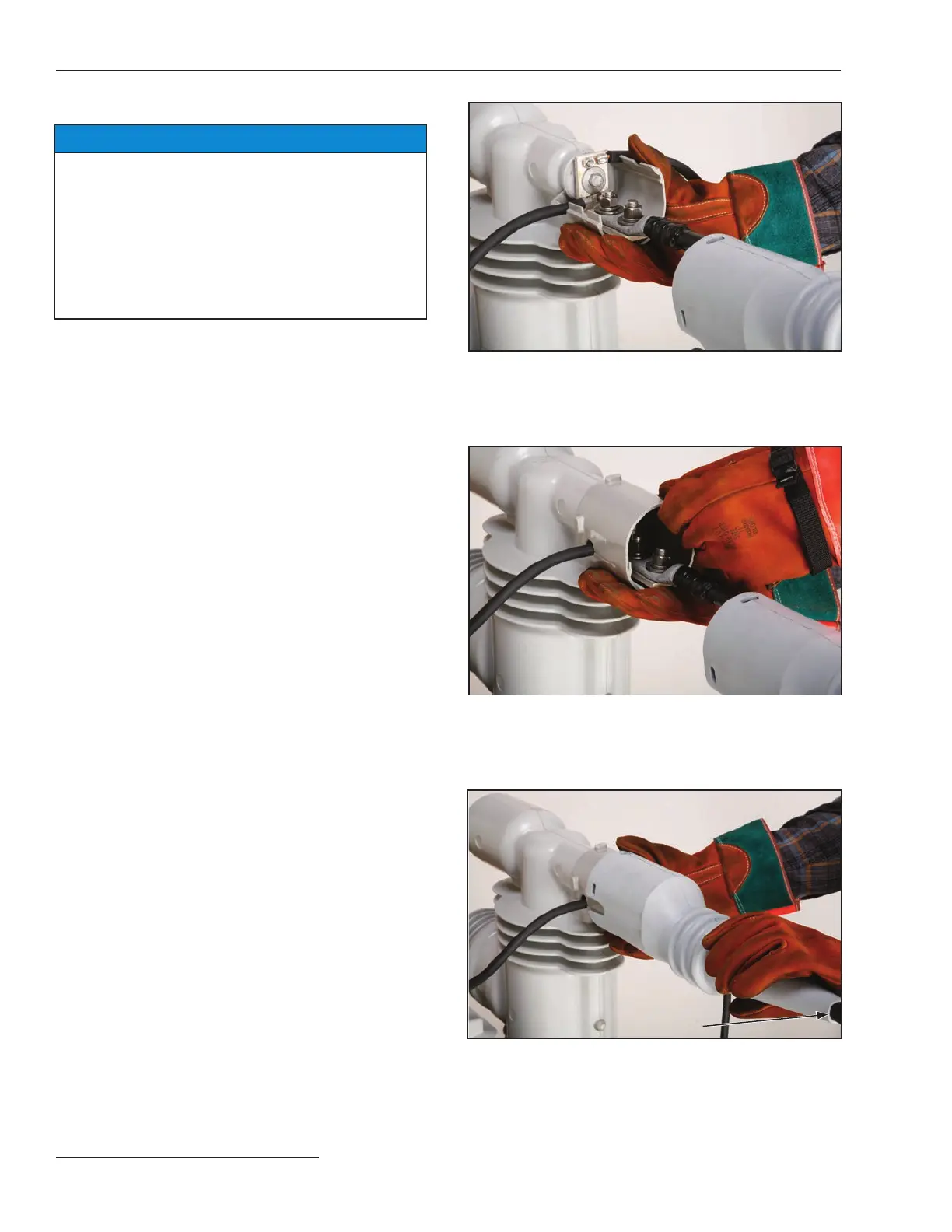
(d) Attach the lower terminal-pad cover (SD-5284) to
the interrupter housing. Conrm the surge
arrester and/or integral power module wires line
up with the bottom half of the hole in the lower
terminal-pad cover. See Figure 10.
(e) Attach the upper terminal pad cover (SD-5283) to
the interrupter housing. It aligns with and
engages the lower cover. If necessary, use tape or
a plastic cable tie to hold the upper and lower
covers together. Conrm the surge arrester and/
or the integral power module wires extend from
the holes in the side of the terminal pad cover
without undue stress or strain. See Figure 11.
(f) Slide the tap cover part way over terminal-pad
cover and remove the tape or cable tie. Slide the
tap cover all the way over the terminal-pad cover
until it snaps into place. A silicone-based
lubricant can be used if the tap cover does not
slide easily. Pins in the terminal-pad cover will
engage the holes in the tap cover. See Figure 12.
Figure 10. Installing lower terminal-pad cover.
Figure 11. Installing upper terminal-pad cover.
Figure 12. Installing tap cover.

 Loading...


