18 S&C Instruction Sheet 766-510
Operation
This section gives an overview of the operation of
the IntelliRupter fault interrupter. For full operating
instructions, see S&C Instruction Sheet 766-540,
“IntelliRupter®PulseCloser® Fault Interrupter:
Operation.”
Establishing a Wi-Fi Communication Link
with an IntelliRupter Fault Interrupter
The Wi-Fi transceiver in the communication module
provides secure wireless point-to-point communication
to a wireless-equipped personal computer operating
under the IEEE 802.11b standard. Transmission range is
typically 150 feet (4572 cm) or less. The Wi-Fi connection
permits local con guration and control of an IntelliRupter
fault interrupter. Further, if a wide-area network radio has
been furnished—and the radio supports con guration
through its serial port—it can be con gured using the
Wi-Fi connection. SpeedNet™ and UtiliNet® Radios
furnished by S&C may be con gured in this manner.
The Wi-Fi transceiver and associated software
provide extensive security features to prevent unauthor-
ized access. These security features are described in
S&C Instruction Sheet 766-523, “Wi-Fi and Security
Administration.”
The communication module must be installed and pow-
ered, and IntelliLink
®
Setup Software must be installed
on your personal computer before a Wi-Fi connection can
be established. To communicate over Wi-Fi:
STEP 1. Open the IntelliLink program: click Start
Programs>S&C>IntelliLink.
STEP 2. Select the Choose an IntelliRupter option.
STEP 3. Select the device name from the drop-down
list or by typing it, or—if security keys have
not been entered—enter the IntelliRupter
fault interrupter serial number by using the
Con gure New IntelliRupter/Wi-Fi option.
Then, click on Connect to IntelliRupter
option.
STEP 4. If the computer is properly con gured and has
the appropriate Wi-Fi security key, the IntelliLink
software will establish a secure Wi-Fi connection
and communicate with the IntelliRupter fault
interrupter.
STEP 5. Log in to IntelliLink software with your
password.
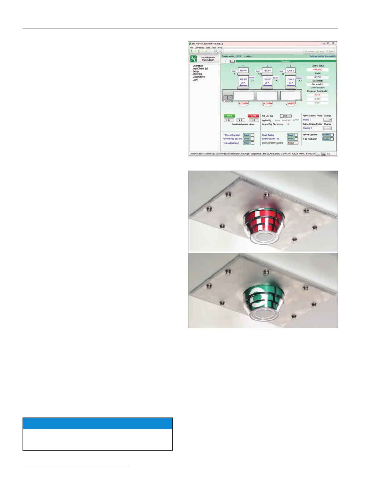
STEP 6. The IntelliRupter fault interrupter Operation
screen will open. See Figure 23.
STEP 7. Con rm the device name shown at Connected
to: at the bottom of the screen is the IntelliRupter
fault interrupter you wish to communicate with.
N OTICE
Target colors are reversed on an IntelliRupter fault
interrupter furnished with Catalog Number Suffix “-F2.”
Figure 23. Operation screen.
Figure 24. Red target with an “I” (top) and green target an “O”
(bottom).
Remote Operation
On the Operation screen, set the Remote Operation
selection box to the Enabled setting. See Figure 23. The
IntelliRupter fault interrupter can now be operated by
remote supervisory control (i.e., SCADA). If applicable, a
dispatcher can test electrical operation of the IntelliRupter
fault interrupter as well as the entire SCADA control path,
including communication.

 Loading...


