S&C ELECTRIC COMPANY
s
INSTRUCTION SHEET
663-503
Page 9 of 35
August 14, 1995
COMPONENTS — Continued
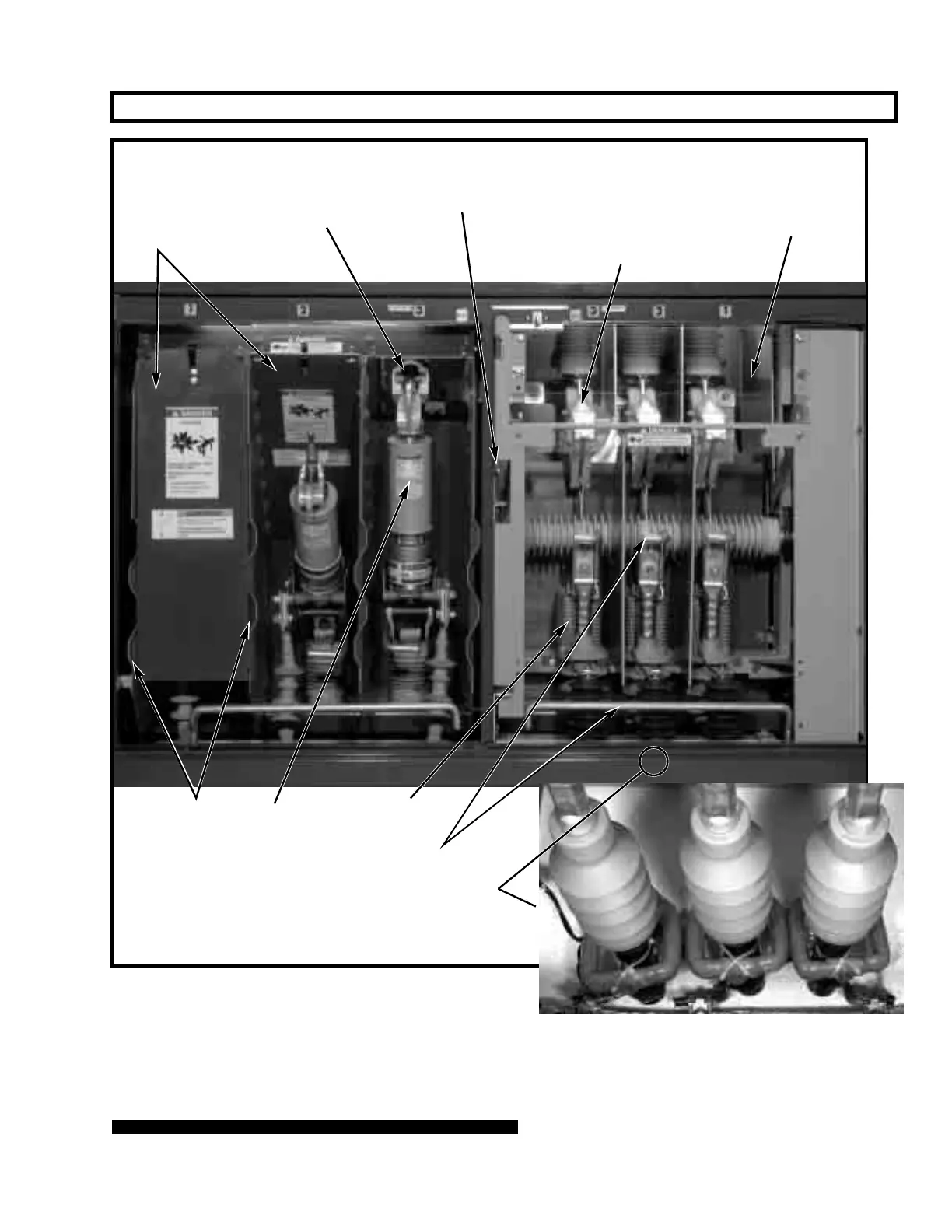
Figure 4. Switch and fuse compartments.
Left-hand door retainer—rotate latch
upward to open door. To secure left-hand
door closed, rotate latch downward over
stop mounted on outer edge of door
Viewing window for visible verifica-
tion of switch position is removable
for phasing. To remove window,
loosen wing-head screws and lift
window off alignment bolts
Current sensors furnished for attach-
ment to each entrance cable when
optional overcurrent-lockout feature
(Catalog Number Suffix “-Y2”) is
included
S&C Voltage
Sensor
S&C Mini-Rupter Switch
S&C Uni-Rupter
Interphase
and end
barriers
S&C Power Fuse
(Fault Fiter Electronic
Power Fuse shown)
Ground studs
Dual-purpose
front barriers